Curtis 1226BL handleiding
Handleiding
Je bekijkt pagina 23 van 124
2 — INSTALLATION AND WIRING
pg. 15
Return to TOC Curtis Model 1226BL – July 2024
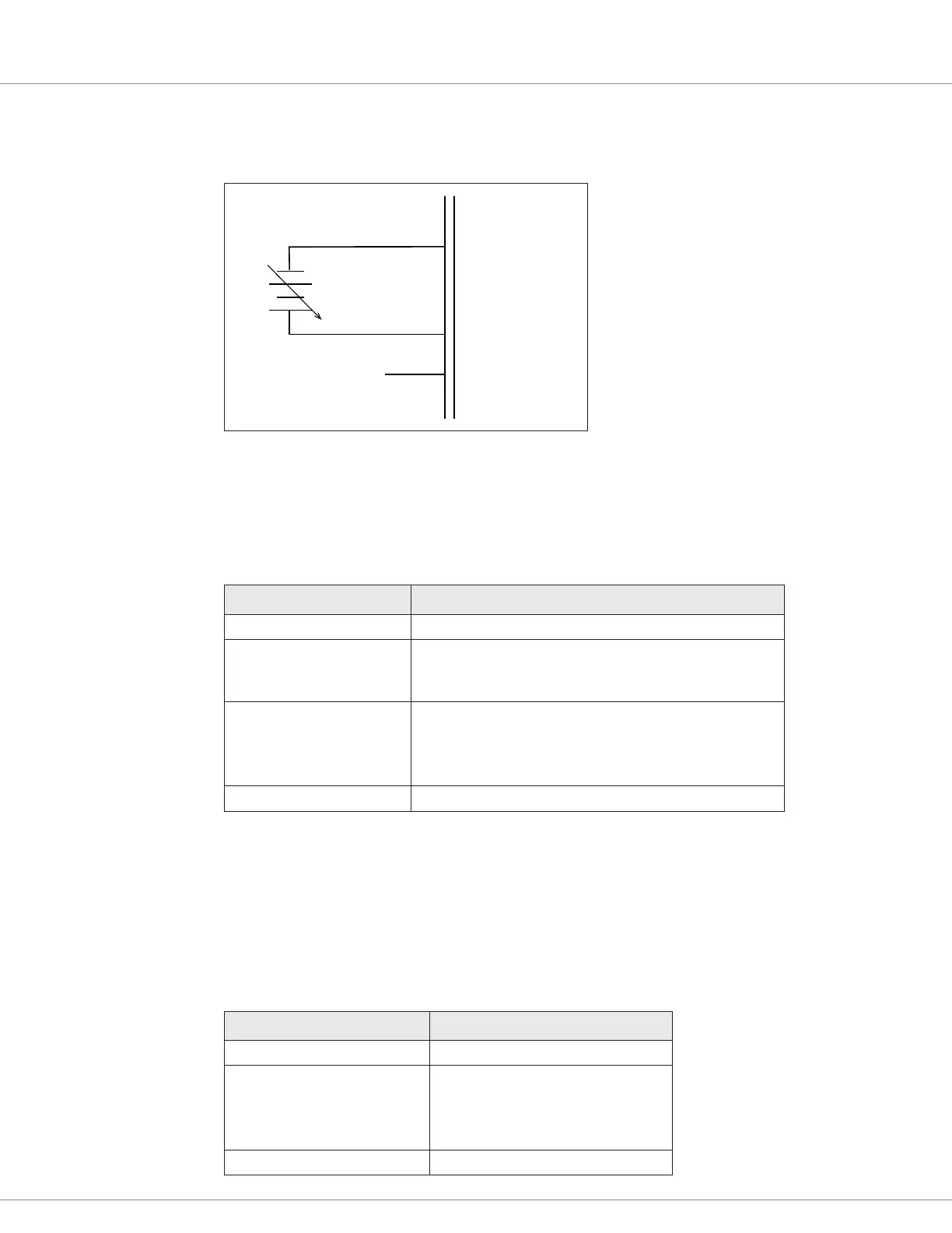
0–5V Voltage Source Throttles
For voltage throttles, connect the 0–5V output signal to the pot wiper input. e negative side of the
voltage source should reference I/O ground as shown in the following diagram:
J3-16
J3-7
POT WIPER
POT HIGH
I/O GND
J3-13
−
+
Keyswitch
e keyswitch is connected to pin J3-1. e keyswitch can be used as the interlock by specifying 1
for the Interlock Type parameter.
e following table describes the specications for the keyswitch input:
Specification Value
Maximum Input Current 8A (maximum pin rating)
Quiescent Current 100mA maximum
Note: This is at full range battery voltage and does not include
current draw from coil loads and external power supplies.
Maximum Voltage Depends upon the model:
• 1226BL-22XX: 34V
• 1226BL-41XX: 63V
• 1226BL-61XX: 105V
Maximum Reverse Voltage −(125% of nominal battery voltage +5V)
Coil Supply Pin
e Coil Supply pin (J3-10) supplies the current for the coil drivers. e pin provides reverse
polarity protection. If power is reversed the controller will prevent coil activation. For a wiring
example, see Figure 6.
Note: e Coil Supply pin is not protected against shorts to B–.
e following table describes the Coil Supply pin’s specications:
Specification Value
Maximum Output Current 8A (maximum pin rating)
Maximum Voltage Depends upon the model:
• 1226BL-22XX: 34V
• 1226BL-41XX: 63V
• 1226BL-61XX: 105V
Maximum Reverse Voltage −0.5V
Bekijk gratis de handleiding van Curtis 1226BL, stel vragen en lees de antwoorden op veelvoorkomende problemen, of gebruik onze assistent om sneller informatie in de handleiding te vinden of uitleg te krijgen over specifieke functies.
Productinformatie
| Merk | Curtis |
| Model | 1226BL |
| Categorie | Niet gecategoriseerd |
| Taal | Nederlands |
| Grootte | 15971 MB |


