Curtis 1220E handleiding
Handleiding
Je bekijkt pagina 12 van 72
2 — INSTALLATION AND WIRING
Curtis Model 1220E – August 2022 Return to TOC
pg. 8
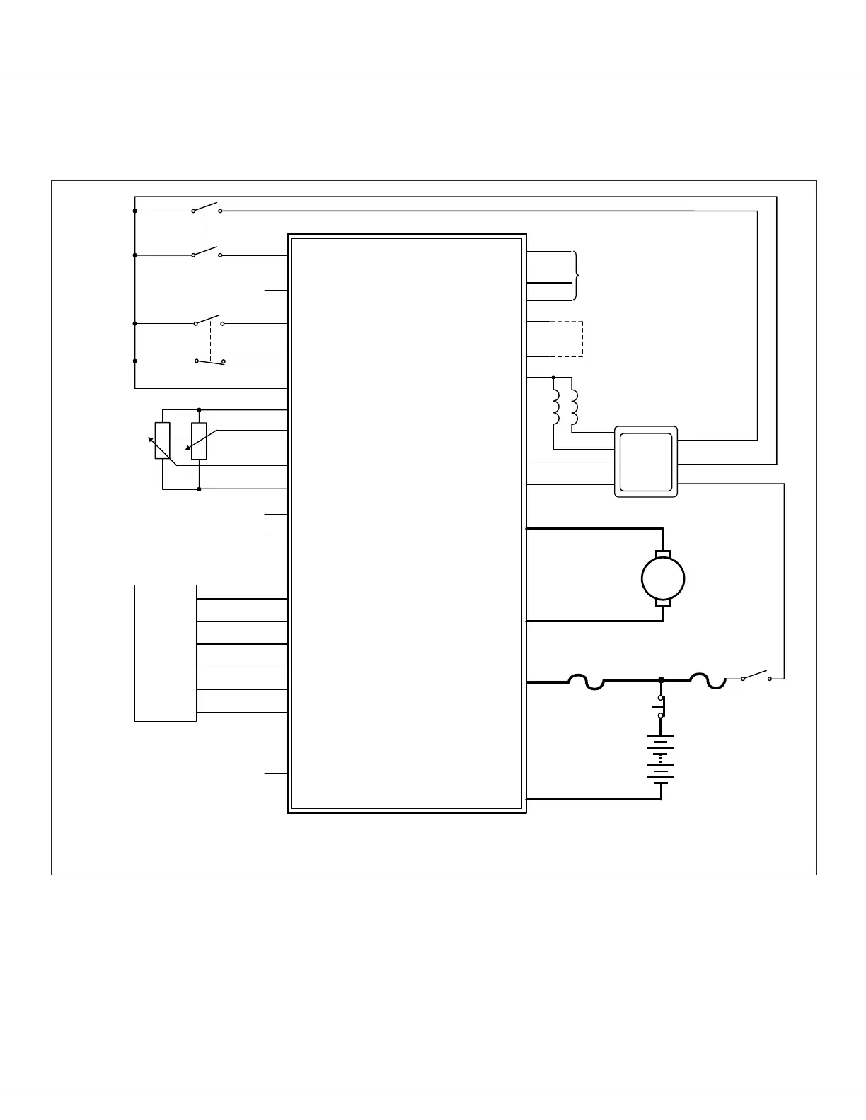
These wiring diagrams (Figures 3a, 3b) show generic applications and may not fully meet the
requirements of your system. You may wish to contact your local Curtis representative to discuss
your particular application.
Figure 3b
Basic wiring diagram, Absolute Position Mode.
EM
Brake
Connect jumper for 120Ω
CANbus termination
Programmer
Interlock Input 2
Interlock Input 1
+12V
Home Switch 1
Home Switch 2
Command Analog 1/Encoder 1A
KSI
I/O GND
I/O GND
Auxiliary Analog Input
+5V Supply 1
+5V Supply 2
Command Analog 2/Encoder 1B
Command Encoder 2A
Command Encoder 2B
Steer Motor Encoder 1A /
Position Analog 1
Steer Motor Encoder 1B /
Position Analog 2
Steer Motor Encoder 2A
Steer Motor Encoder 2B
Tx
Rx
I/O GND
CAN TERM H
CAN L
CAN L
CAN H
Fault Output
J1-4
J1-3
J1-2
J1-1
J2-7
J3-12
J3-12
J3-1
J3-8
Traction Main
Contactor Coil
Main Driver
Interlock
Coil Return
KSI
EM Brake Driver
CAN H
CAN L
Curtis
AC
Traction
Controller
M
M1
M2
B+
B−
Power Fuse
Control Fuse
Keyswitch
Emergency
Stop
Battery
Interlock
Switch
Home
Switch
Steer Command
Pots
Dual
Steer Motor
Encoder
J3-4
J2-2
J3-3
J2-1
N.O.
N.C.
J3-5
J3-7
J3-6
J3-13
J2-3
J2-4
J3-14
J3-11
J3-2
J3-9
J2-5
J2-6
J3-10
J2-8
1220E Controller
Bekijk gratis de handleiding van Curtis 1220E, stel vragen en lees de antwoorden op veelvoorkomende problemen, of gebruik onze assistent om sneller informatie in de handleiding te vinden of uitleg te krijgen over specifieke functies.
Productinformatie
| Merk | Curtis |
| Model | 1220E |
| Categorie | Niet gecategoriseerd |
| Taal | Nederlands |
| Grootte | 9449 MB |


