Curtis 1212P handleiding
Handleiding
Je bekijkt pagina 11 van 51
2 — INSTALLATION AND WIRING
pg. 7
Return to TOC 1212P Manual – Sept. 2022
THROTTLE WIRING
Either a 3-wire potentiometer throttle or a voltage throttle can be used with the controller. e
controller can accept a single-ended, inverse single-ended, wigwag, inverse wigwag, or unipolar input
signal from the throttle, depending on how the rottle Type parameter is programmed; see page 17.
rottle wiring is described in the following text. If the throttle you are planning to use is not covered,
contact the Curtis office nearest you.
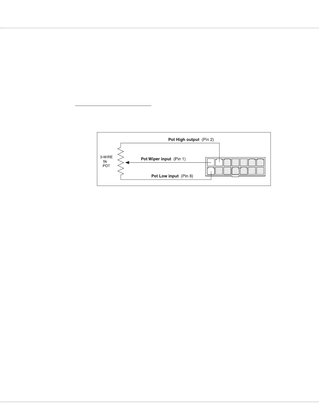
5kΩ, 3-Wire Potentiometer
A 5kΩ, 3-wire potentiometer is shown in the wiring diagrams (Figure 3) as well as in Figure 4. With
this throttle, the controller can be programmed for a rottle Type 0–4 input signal; see page 17.
1234567
8910 11 12 13 14
Ω
Figure 4
Wiring for 3-Wire,
5KΩ Potentiometer
rottle.
For wigwag, inverted wigwag, and unipolar applications, the pot can be correctly centered within the
controller’s neutral band by using the throttle autocalibration feature (see page 19).
e controller provides full pot fault protection against open or shorted wires anywhere in the
throttle assembly. e overall pot resistance should be 4.3 to 7.0 kΩ. Values outside this range will
trigger a fault condition. If a pot fault occurs while the vehicle is moving, the controller will decelerate
the vehicle to a smooth stop using the decel rate set by the Key O Decel parameter. If the fault is
corrected while the throttle is still applied, an HPD fault will be issued and driving is disabled until
throttle is reduced to neutral.
Bekijk gratis de handleiding van Curtis 1212P, stel vragen en lees de antwoorden op veelvoorkomende problemen, of gebruik onze assistent om sneller informatie in de handleiding te vinden of uitleg te krijgen over specifieke functies.
Productinformatie
| Merk | Curtis |
| Model | 1212P |
| Categorie | Niet gecategoriseerd |
| Taal | Nederlands |
| Grootte | 5521 MB |


