Curtis 1212P handleiding
Handleiding
Je bekijkt pagina 10 van 51
2 — INSTALLATION AND WIRING
1212P Manual – Sept. 2022 Return to TOC
pg. 6
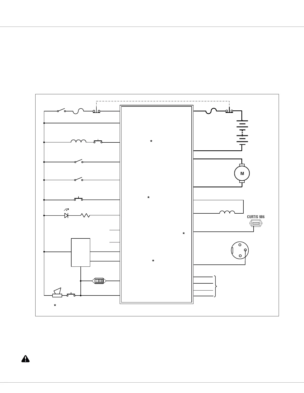
WIRING: STANDARD INSTALLATION
e wiring diagram presented in Figure 3 shows a typical installation for a pallet truck application.
is installation is shown with a Curtis electronic throttle. e inhibit input can be wired into
the circuit in various ways; in the standard installation shown here it serves as an interlock (see
pin J1-6), and is B+ inactive (Inhibit Type parameter set to 4).
e J2 connector can be used interchangeably for the programmer or for the charge inhibit.
Figure 3
Standard Wiring Configuration, Curtis 1212P Controller.
INTERLOCK
KEYSWITCH
CONTROL
FUSE
M2
M1
INTERLOCK SW
(Inhibit Type = 4)
J1-8
J3-1
B–
B+
POWER
FUSE
BATTERY
Programmer
1212P Controller
MODE (M1,M2)
J1-4
J1-2
J1-13
J1-1
J1-6
J2-4
J2-3
J2-2
J2-1
B+
I/O GND
Tx
Rx
MOTOR
CURTIS
ET-19XX
J1-5
KSI
EMERGENCY
STOP
MODE SW
STATUS LED
NEUTRAL INPUT
EMERGENCY
REVERSE
EM REV SW
J1-14
PUMP CONTACTOR
COIL
LIFT LOCKOUT
OUTPUT
I/O GND
POT WIPER
J1-3
J1-11
BDI
BDI(0-5V)
J3-2
BRAKE +
BRAKE –
EM BRAKE
LIFT LOCKOUT
INPUT
J1-9
PIN3
B+
B–
CHARGE INHIBIT
J2-3
CHARGER
SOCKET
J1-12
J1-10
POT HIGH
J1-7
B+
POT LOW
HORN
KSI
GND
0.5V-4.5V
Neutral
LIFT SW
HORN
SW
EMERGENCY
STOP
STATUS LED
R
(Throttle Type = 5)
Must match the parameter
e polarity of the motor M1 and M2 connections will aect the operation of the emergency reverse
feature. e forward and reverse switches and the M1 and M2 connections must be congured so
that the vehicle drives away from the operator when the emergency reverse button is pressed.
CAUTION
Bekijk gratis de handleiding van Curtis 1212P, stel vragen en lees de antwoorden op veelvoorkomende problemen, of gebruik onze assistent om sneller informatie in de handleiding te vinden of uitleg te krijgen over specifieke functies.
Productinformatie
| Merk | Curtis |
| Model | 1212P |
| Categorie | Niet gecategoriseerd |
| Taal | Nederlands |
| Grootte | 5521 MB |


