Curtis 1212 handleiding
Handleiding
Je bekijkt pagina 10 van 47
2 — INSTALLATION AND WIRING
1212 Manual – Sept. 2022 Return to TOC
pg. 6
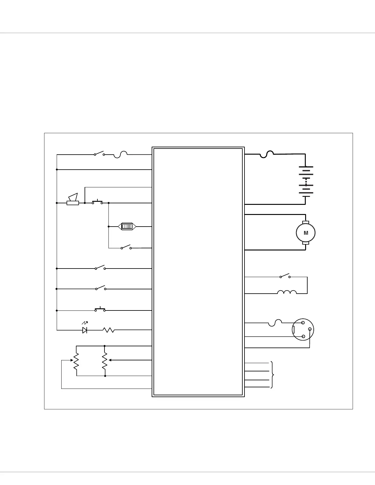
WIRING: STANDARD INSTALLATION
e wiring diagram presented in Figure 3 shows a typical installation for a DME application. is
installation is shown with a single-ended 3-wire 5kΩ potentiometer throttle and a reverse switch.
With wigwag throttles, a reverse switch is not used and Pin J1-12 is le unconnected.
e optional speed inhibit input can be wired into the circuit in various ways; in the standard
installation shown here, it is B‒ active (Inhibit Type parameter set to 0).
e J2 connector can be used interchangeably for the programmer or for the battery charger.
Figure 3
Standard Wiring Configuration, Curtis 1212 Controller.
SPEED INHIBIT
KEYSWITCH
CONTROL
FUSE
M2
M1
J1-8
J3-1
B–
B+
POWER
FUSE
BATTERY
Programmer
1212 Controller
MODE (M1,M2)
J1-4
J1-2
J1-1
J1-6
J2-4
J2-3
J2-2
J2-1
B+
I/O GND
Tx
Rx
MOTOR
J1-5
KSI
MODE SW
STATUS LED
REVERSE
PUSH
PUSH SW
J1-14
HORN
I/O GND
POT WIPER
J1-3
J1-11
BDI(0-5V)
J3-2
BRAKE +
BRAKE –
EM BRAKE
J1-9
B+
B–
CHARGE INHIBIT
J2-3
CHARGER
SOCKET
J1-10
POT HIGH
J1-7
B+
POT LOW
HORN SW
STATUS LED
R
HORN
INHIBIT SW
J2-4
J2-2
B+
I/O GND
BRAKE SW(optional)
J1-12
REVERSE SW
J1-13
5KΩ
THROTTLE
POT
100kΩ
SPEED
POT
SPEED LIMIT POT
Bekijk gratis de handleiding van Curtis 1212, stel vragen en lees de antwoorden op veelvoorkomende problemen, of gebruik onze assistent om sneller informatie in de handleiding te vinden of uitleg te krijgen over specifieke functies.
Productinformatie
| Merk | Curtis |
| Model | 1212 |
| Categorie | Niet gecategoriseerd |
| Taal | Nederlands |
| Grootte | 5028 MB |


