Crestron CLTI-1MC4 handleiding
Handleiding
Je bekijkt pagina 3 van 6
Crestron CLTI- & CLXI-1MC4 Terminal Block & Module
Module Installation
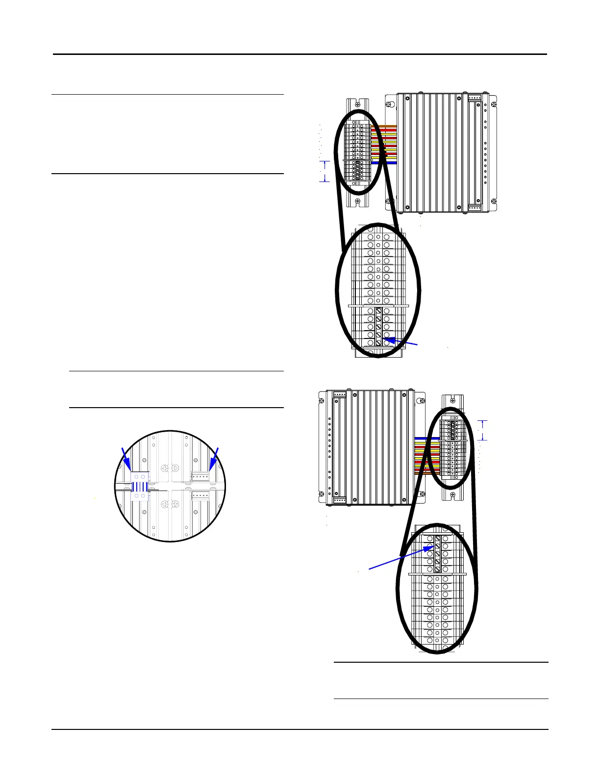
Wiring Diagram of the Terminal Block to the Module
(Single-wide and Left Side Double-wide Enclosures)
JUMPER INSTALLED
RED
BROWN
YELLOW
RED
YELLOW
RED
YELLOW
RED
YELLOW
JUMPER ON BLUE
SECTION REMAINS
INSTALLED.
BLUE
ENLARGEMENT DETAIL:
CAUTION: Module contains electrostatic sensitive
devices (ESDs); unit must be handled from metal chassis
– do not touch PC board or components.
NOTE: Modules are to be installed after enclosure has
been completely wired. Refer to the terminal block
installation procedure on page 2 for details.
1. Use the four supplied self-tapping pan Phillips
screws (8B x ¼-inch (6 mm) length) to secure
the module to the enclosure.
2. As shown in the wiring diagrams (next column),
connect the wires from the module to the
terminal block. Each wire exits the module
directly in line with, and is the same color as, the
terminal to which it should be connected. Wires
are pre-stripped to 12 mm. Tighten to 1 Nm.
3. If the module is being installed above another
module within the enclosure, attach the supplied
module interconnect cable between the two
modules. The illustration below depicts the area
within a double-wide enclosure where the
corners of four modules meet.
Wiring Diagram of the Terminal Block to the Module
(Right Side Double-wide Enclosures)
NOTE: One wire on the module interconnect cable
may be a different color from the rest. The color has
no bearing on its orientation during installation.
JUMPER INSTALLED
RED
BROWN
BLUE
YELLOW
RED
YELLOW
RED
YELLOW
RED
YELLOW
JUMPER ON BLUE
SECTION REMAINS
INSTALLED.
ENLARGEMENT DETAIL:
Use Module Interconnect Cable to Wire Module to Module
MODULE
INTERCONNECT
CABLE ATTACHED
CONNECTION
NOT
MADE
4. Turn on the circuit breaker and verify that the
green PWR LED on the module lights and the
breaker does not trip.
NOTE: Power must be supplied to LINE for the
module to communicate with the control system or
for any of the circuits to operate.
Installation Guide – DOC. 6409A Terminal Block & Module: CLTI- & CLXI-1MC4 • 3
Bekijk gratis de handleiding van Crestron CLTI-1MC4, stel vragen en lees de antwoorden op veelvoorkomende problemen, of gebruik onze assistent om sneller informatie in de handleiding te vinden of uitleg te krijgen over specifieke functies.
Productinformatie
| Merk | Crestron |
| Model | CLTI-1MC4 |
| Categorie | Niet gecategoriseerd |
| Taal | Nederlands |
| Grootte | 969 MB |


