Chauvin Arnoux C.A 6503 handleiding
Handleiding
Je bekijkt pagina 17 van 57
English
C.A 6503 17
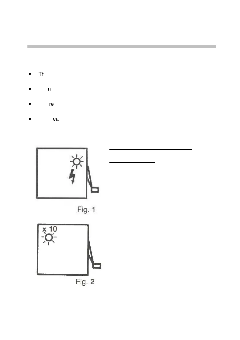
A red indicator (Fig. 2) on the left side of
the instrument indicates the automatic
change of range. When it is lit, multiply the
reading by 10 to obtain the result.
Measurement input terminals:
These
accept safety plugs 4mm in diameter.
Other indicators:
A green indicator (Fig. 1) on the right side
of the instrument indicates that the speed
of the magneto is correct. When it is lit, the
voltage betwee
n the terminals of the
instrument is 250V, 500V, or 1000VDC
(no-
load), depending on the setting of the
switch.
3. USE AND CHARACTERISTICS:
3.1. RECOMMENDATIONS
The needle must indicate 0 on the 600-scale when at rest; if not, adjust it
using the black screw in the centre (see picture above).
Do not connect the instrument to the terminals of a circuit of which the
voltage exceeds 600V
AC
or
DC
.
Before any resistance measurement, check that the circuit is not live (switch
set to 500V before connection).
After each insulation resistance measurement, let the circuit discharge
(needle on 0V; this takes a few seconds) before disconnecting the
instrument.
Bekijk gratis de handleiding van Chauvin Arnoux C.A 6503, stel vragen en lees de antwoorden op veelvoorkomende problemen, of gebruik onze assistent om sneller informatie in de handleiding te vinden of uitleg te krijgen over specifieke functies.
Productinformatie
| Merk | Chauvin Arnoux |
| Model | C.A 6503 |
| Categorie | Niet gecategoriseerd |
| Taal | Nederlands |
| Grootte | 5138 MB |


