Carel pCO5 handleiding
Handleiding
Je bekijkt pagina 17 van 48
17
ENG
pCO5plus +0300020EN rel. 1.9 - 28.03.2025
Electrical installation
Important: Before servicing the equipment in any way disconnect
the controller from the power mains by putting the system’s main switch
on OFF.
Make sure the system is provided with a power disconnector conforming
to regulations. Use cable lugs that are suitable for the terminals used.
Loosen each screw and insert the cable lugs, then tighten the screws.
There is no limit to the number of wires that can be connected to
each individual terminal. When tightening the terminal screws apply
a tightening torque no greater than 0.6 Nm. For information on the
maximum allowable length of the connections to the analogue/digital
inputs and to the analogue outputs please refer to the “Technical
Speci cations” table. In environments subject to strong disturbance use
shielded cables with the braiding bonded to the earthing conductor
in the electrical panel. The terminals can accept wires with a maximum
cross-section of 2.5 mm2 (12 AWG). After making the connection, gently
tug on the cables to make sure they are su ciently tight.
Notice:
• secure the cables connected to the controller with clamps placed at 3
cm from the connectors;
• if the power transformer's secondary winding is earthed, make sure
the earth conductor is bonded to the conductor that goes to the
controller and is connected to terminal G0. This applies to all the
devices connected to the controller through a serial network.
Important:
• Using a supply voltage other than speci ed can seriously damage the
system.
• Connect the fuse close to the controller.
• Installing, servicing and inspecting the controller should be done
only be quali ed personnel and in compliance with national and local
regulations.
• All the very low voltage connections (24 Vac/Vdc or 28 to 36 Vdc
analogue and digital inputs, analogue outputs, serial bus connections,
power supplies) must have reinforced or double insulation from the
power mains.
• Avoid touching or nearly touching the electronic components
mounted on the boards to avoid electrostatic discharges from the
operator to the components, which can be very damaging.
• Do not press the screwdriver on the connectors with excessive force,
to avoid damaging the controller.
• Using the device in any way other than speci ed by the Manufacturer
can compromise its protection system.
• Use only optional boards and connectors supplied by CAREL;
• When handling CAREL products, the use of an antistatic bracelet or
electrostatic dissipating footwear is recommended.
4.3 Preliminary operations
Installing the serial cards
If the Fieldbus and BMS serial cards built into the pCO5+ are insu cient
for the required application, you can add a Fieldbus serial port and a BMS
serial port, which are available as accessories (see chap.1).
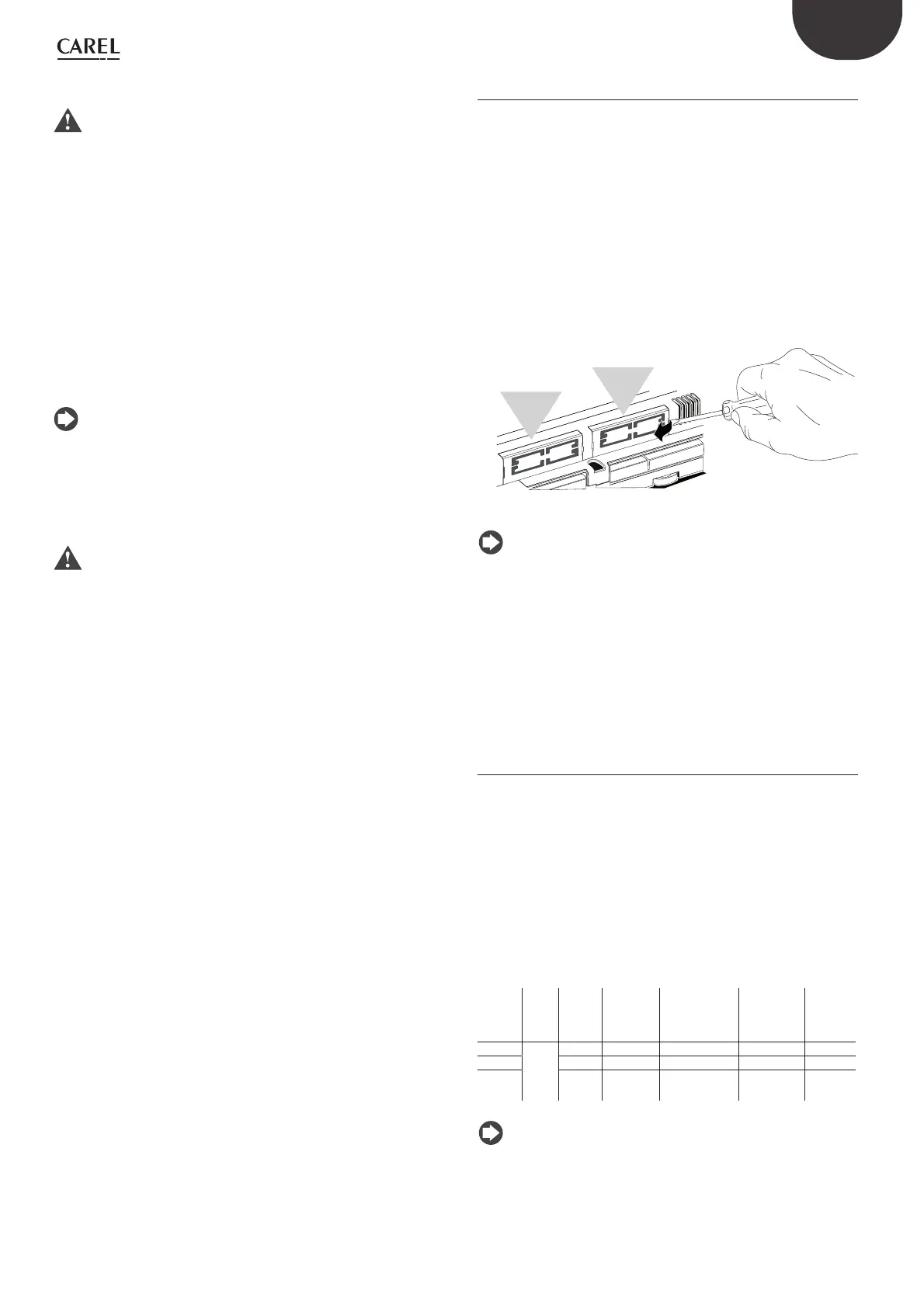
To install them, proceed as follows:
1. Locate the Fieldbus or BMS serial port.
2. Using a screwdriver, take o the cover.
3. Using a pair of nippers, cut out the perforated plastic part to create
an opening.
4. Plug the optional card into the edge-card connector, making sure it
is rmly secured and makes contact.
5. Put back the cover so that the serial card’s connector is aligned with
the opening.
6. Make the electrical connections required.
FieldBus card
BMS card
Fig. 4.b
Notice: For details, refer to the instructions sheets of the cards to
install.
Installing the pCOe expansion card
See instructions sheet code +050003265.
Installing the Ultracap module
See instructions sheets codes +0500042IE and +0500041IE.
4.4 Serial network electrical
connections
To improve the controller’s immunity against electromagnetic
interference, the serial connection cable should be a shielded twisted
pair cable, 2-pole or 3-pole depending on the insulation of the serial
connection. The following rule applies:
• if the serial port is isolated (functionally) from the power supply, a third
wire is required in the serial cable to act as a common reference for the
controllers. If the serial port is not optically isolated and the common
reference is already present, no third wire is required.
Technical speci cations for connections
Use a shielded, twisted pair cable (AWG 20-22) with inter-conductor
capacitance <90pF/m.
Main
device
HW Lmax
(m)
Wire/wire
capacitan-
ce (pF/m)
Resistance on
rst and last
devices
Max. no. of
Secondary
devices on
bus
Data rate
(bit/s)
FBUS
RS485
1000
< 90 120 Ω 64 19200
PC 1000
< 90 120 Ω 207 38400
pLAN 500
< 90 - 32
62500/
115200
Tab. 4.b
Notice: In case of a Main–Secondary network the max. allowable
length is 1000 m. If the network is longer than 100 m, apply 120Ω, 1/4W
terminating resistors to the rst and last devices in the network.
Bekijk gratis de handleiding van Carel pCO5, stel vragen en lees de antwoorden op veelvoorkomende problemen, of gebruik onze assistent om sneller informatie in de handleiding te vinden of uitleg te krijgen over specifieke functies.
Productinformatie
| Merk | Carel |
| Model | pCO5 |
| Categorie | Niet gecategoriseerd |
| Taal | Nederlands |
| Grootte | 10234 MB |

