Carel iJW handleiding
Handleiding
Je bekijkt pagina 16 van 104
16
ENG
iJW +0300103EN rel. 1.1 - 31.03.2025
Index
2.9 Serial port connections
For serial connections (FieldBus and BMS ports), the cables used must be suitable for the RS485 standard (shielded twisted pair,
see the specifi cations in the following table).
Main device Serial port Lmax (m)
Wire/wire
capacitance (pF/m)
Resistance on last device
Max secondary devices
on bus
Data rate (bit/s)
PC (supervision) BMS 500 <90 120 Ω - 19200 (*)
PC (supervision) TTL 2 <90 - - 19200 (*)
Tab. 2.j
(*) modifi able by parameter.
Caution: connect the shield to the GND of the control, do not connect GND to earth. Connect a 120 Ω terminating resistor
between the Tx/Rx+ and Tx/Rx- terminals on the last controller on the RS485 line.
2.10 Installation
For installation proceed as follows, with reference to the wiring diagrams:
• before performing any operations on the control board, disconnect the main power supply by turning the main switch in the
electrical panel OFF;
• avoid touching the control board, as electrostatic discharges may damage the electronic components;
• the index of protection required for the application must be ensured by the manufacturer of the cabinet or by suitable as-
sembly of the controller;
• connect any digital inputs, Lmax = 10 m;
• connect the actuators: the actuators should only be connected after having programmed the controller. Carefully evaluate
the maximum ratings of the relay outputs as indicated in “Controller electrical and physical specifi cations”;
• program the controller: see “User interface”;
• for safety devices (e.g. circuit breakers), comply with the following requirements:
– IEC 60364-4-41;
– standards in force in the country;
– connection technical requirements of the power company.
Caution: the following warnings must be observed when connecting the controllers:
• incorrect connection to the power supply may seriously damage the controller;
• use cable ends suitable for the corresponding terminals. Loosen each screw and insert the cable ends, then tighten the screws
and lightly tug the cables to check correct tightness;
• separate as much as possible the probe and digital input cables from cables to inductive loads and power cables, so as to
avoid possible electromagnetic disturbance. Never run power cables (including the electrical panel cables) and probe signal
cables in the same conduits;
• do not install the probe cables in the immediate vicinity of power devices (contactors, circuit breakers, etc.). reduce the path
of probe cables as much as possible, and avoid spiral paths that enclose power devices.
3. CONFIGURATION TOOLS
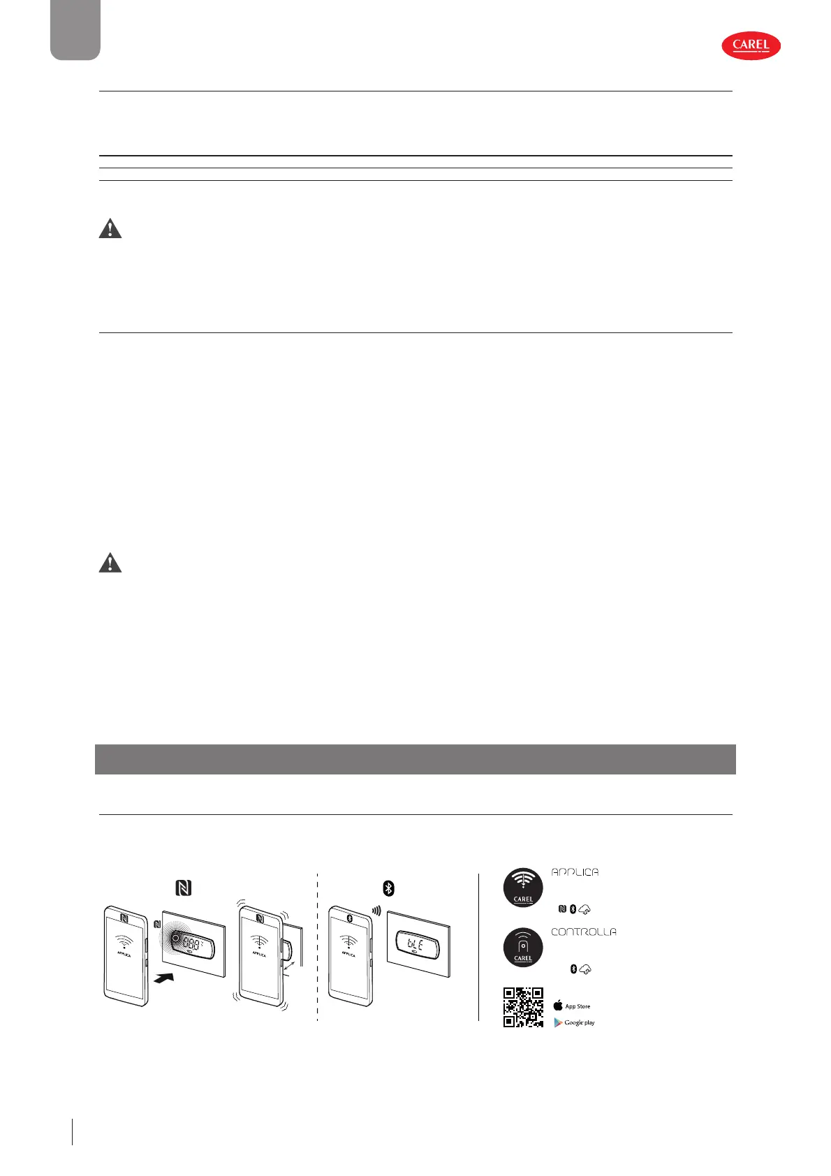
3.1 Applica and Controlla apps
The Carel apps can be used to confi gure the controller from a mobile device (smartphone, tablet), via NFC (Near Field Commu-
nication) or BLE (Bluetooth™ Low Energy). Supported devices: Android 7, iOS 11; Bluetooth™ 4.0, and higher.
300100_028_R01
BLE
NFC
max
10mm
CAREL APPs
Local and remote
technical app
for Service
Local and remote
new interaction app
for End users
Fig. 3.a
Bekijk gratis de handleiding van Carel iJW, stel vragen en lees de antwoorden op veelvoorkomende problemen, of gebruik onze assistent om sneller informatie in de handleiding te vinden of uitleg te krijgen over specifieke functies.
Productinformatie
| Merk | Carel |
| Model | iJW |
| Categorie | Niet gecategoriseerd |
| Taal | Nederlands |
| Grootte | 14964 MB |


