Carel Hecu handleiding
Handleiding
Je bekijkt pagina 11 van 60
11
Hecu +0300023EN rel. 1.2 - 14.12.2021
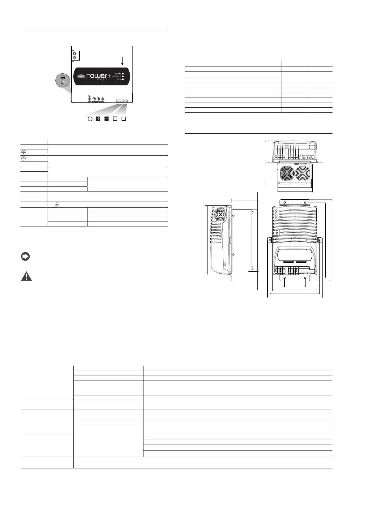
2.4 PSD2 18-24 A three-phase inverter
For further details on the electrical and mechanical specifi cations, see
technical leafl et +0500125IE
UVW
C1
C2
power
run-fault
data
E
STO
A B
GND
+
-
Tx/Rx
F
Fig. 2.i
Description of the terminals:
Ref. Description
L3, L2, L1 Three-phase power supply
(*)
(*)
Motor output
U, V, W
C1 Optional external choke
C2
GND GND (0 V) RS485/ModBus® connection
three-pin plug-in connector
+ Tx/Rx+
- Tx/Rx-
A STO safety digital input (**)
2-pin plug-in connector
B
E
PE
earth screw
F (LEDS) POWER (green) drive powered
RUN (green) drive running
FAULT (red) drive alarm
DATA (yellow) communication active
Tab. 2.d
(*) The earth connections inside the controller are electrically connected together
and to PE.
(**) Voltage-free digital input: if not used, short-circuit with a jumper.
Notice: RS485 and STO connections have reinforced insulation
from the power supply.
Caution:
• in the European Union, all units that incorporate the drive must
comply with the Machinery Directive 2006/42/EC. Specifi cally, the
manufacturer of the unit is responsible for installing a main switch and
conformity to standard EN 60204-1;
• for a fi xed installation, according to local regulations in force, a circuit
breaker may be required between the power supply and the drive;
• the drive must be connected to earth: the earth cable must be sized
for the maximum fault current, which will normally be limited by fuses
or a circuit breaker.
Rated values
The following table shows the rated input current and output current
values, as well as the specifi cations for sizing the cables (cross-section,
maximum length) and the fuses. The values refer to an operating
temperature of 60°C and a switching frequency of 8 kHz, unless otherwise
specifi ed.
Models PSD2 18 A PSD2 24 A
Rated input current at 400 V
18.5-16.5 A 21.1-21 A
Fuse or type B circuit breaker
32 A 32 A
Power cable size
4 mm
2
6 mm
2
Rated output current
18 A 24 A
Rated output power at 400V
10.5 kW 14 kW
Maximum total dissipation
320 W 485 W
Maximum dissipation on the heat sink
250 W 380 W
Min. motor cable size
4 mm
2
4 mm
2
Max. motor cable length
5 m 5 m
Dimensions (mm)
316
131
136
8782
269.2
289,2
80
172
192,3
213
240 24.6
24.6
Fig. 2.j
Main technical specifi cations
Environmental conditions Storage temperature -40T60°C
Operating temperature -20T60 °C
Humidity < 95% RH non-condensing
Altitude
Maximum allowed: 2000 m above sea level
Up to 1000 m asl without derating
Derating in terms of maximum output current: 1% /100m
Environmental pollution level 3
Power supply
Input voltage
PS2**183*****, PS2**243*****: 200 - 240Vac -10%/ +10%, 50 - 60Hz, 3 ~
~
PS2**184*****, PS2**244*****: 380 - 480Vac -10%/ +10%, 50 - 60Hz, 3 ~
~
Motor output
Output voltage 0 - Input voltage
Output frequency 0 - 500 Hz
Frequency resolution 0.1 Hz
Maximum cable length see paragraph 5.1
Switching frequency 4, 6, 8 kHz
Functions
Protection functions
Drive: short circuit, overcurrent, earth fault, overvoltage and undervoltage, overtemperature
Motor: overload (150% Inom for 1 minute), stall
System: loss of communication,
Safety: STO (safe torque off ), locked rotor
Control unit
Each drive must be connected in the network via Modbus® to a CAREL pCO or other manufacturer’s controller that manages the drives with
Main/Secondary logic.
Bekijk gratis de handleiding van Carel Hecu, stel vragen en lees de antwoorden op veelvoorkomende problemen, of gebruik onze assistent om sneller informatie in de handleiding te vinden of uitleg te krijgen over specifieke functies.
Productinformatie
| Merk | Carel |
| Model | Hecu |
| Categorie | Niet gecategoriseerd |
| Taal | Nederlands |
| Grootte | 10743 MB |


