Audibax Control 384 handleiding
Handleiding
Je bekijkt pagina 4 van 16
USER´S
MANUAL
Control 384
3 12
4. APPENDIX
4.1 DMX Primer
There are 512 channels in a DMX-512 connection. Channels may be assigned in any manner.
A fixture capable of receiving DMX 512 will require one or a number of sequential channels.
The user must assign a starting address on the fixture that indicates the first channel reserved
in the controller. There are many different types of DMX controllable fixtures and they all may
vary in the total number of channels required. Choosing a start address should be plann¬ed
in advance. Channels should never overlap. If they do, this will result in erratic operation of
the fixtures whose starting address is set incorrectly. You can however, control multiple
fixtures of the same type using the same starting address as long as the intended result is that
of unison movement or operation. In other words, the fixtures will be slaved together and all
respond exactly the same.
DMX fixtures are designed to receive data through a serial Daisy Chain. A Daisy Chain
connection is where the DATA OUT of one fixture connects to the DATA IN of the next fixture.
The order in which the fixtures are connected is not important and has no effect on how a
controller communicates to each fixture. Use an order that provides for the easiest and most
direct cabling. Connect fixtures using shielded two conductor twisted pair cable with three
pin XLR male to female connectors. The shield connection is pin 1, while pin 2 is Data
Negative (S-) and pin 3 is Data positive (S+).
4.2 Fixture Linking
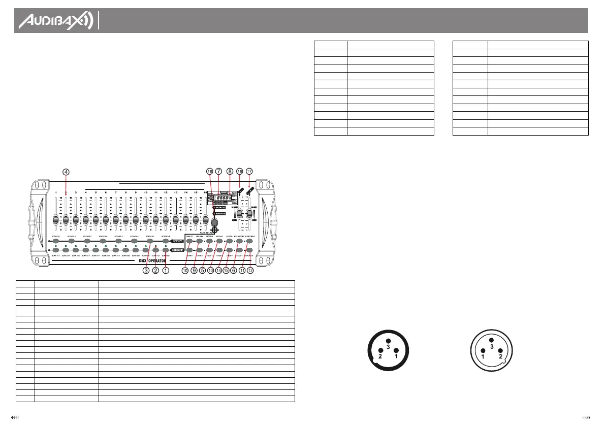
Occupation of the XLR-connection:
Caution: At the last fixture, the DMX-cable has to be terminated with a terminator. Solder a
1200 resistor between Signal (-) and Signal (+) into a 3-pin XLR-plug and plug it in the
DMX-output of the last fixture.
DMX-OUTPUT
XLR mounting-socket:
1- Ground
2- Signal (-)
3- Signal (+)
DMX-OUTPUT
XLR mounting-plug:
1- Ground
2- Signal (-)
3- Signal (+)
• Built-in microphone for music mode
• Auto mode program controlled by fade time sliders *DMX in/out: 3pinXRL
• LED gooseneck lamp
• Plastic end housing
2.2 General Overview
• The Controller is a universal intelligent lighting controller. It allows the control of 24 fixtures
composed of 16 channels each and up to 240 programmable scenes. Six chase banks can
contain up to 240 steps composed of the saved scenes and in any order. Programs can be
triggered by music, midi, automatically or manually. All chases can be executed at the
same time.
• On the surface you will find various programming tools such as 16 universal channel sliders,
quick access scanner and scene buttons, and an LED display indicator for easier navigation
of controls and menu functions.
2.3 Product Overview (front)
Item
Button or Fader
Function
1
Scanner select buttons
Fixture selection
2
Scanner indicator LEDS
Indicates the fixtures currently selected
3
Scene select buttons
Universal bump buttons representing scene location for storage and selection
4 Channel faders
For adjusting DMX values, Ch. 1~16 can be adjusted immediately after pressing the
respective scanner select button
5
Program button
Used to enter programming mode
6
Music/Bank Copy button
Used to activate Music mode and as the copy command during programming
7
LED display window
Status window displays pertinent operational data
8
Mode Indicator LEDS
Provides operating mode status, (manual, music or auto)
9
Bank Up button
Function button to traverse Scene/ Steps in banks or chases
10
Bank Down button
Function button to traverse Scene/ Steps in banks or chases
11
Tap Display button
Sets the chase speed by tapping, and toggles between values and percentages.
12
Blackout button
Sets the shutter or dimmer value of all fixtures to "0" causing all light output to cease
13
Midi/ADD button
Activates MIDI external control and also used to confirm the record/save process
14
Auto/Del button
Used to activate Auto mode and as the delete function key during programming
15
Chaser buttons
Chase memory 1 ~6
16
Speed fader
This will adjust the hold time of a scene or a step within a chase
17
Fade-Time fader
Also considered a cross-fade, sets the interval time between two scenes in a chase
18
Page select button
In manual mode, press to toggle between pages of control
MIDI NOTE
FUNCTION (TURN ON/OFF)
MIDI NOTE
FUNCTION (TURN ON/OFF)
00 to 07
Scenes 1~8in BANK1
00 to 07
Scenes 1~8in BANK 12
08 to 15
Scenes 1~8in BANK 2
08 to 15
Scenes 1~8 in BANK 13
16 to 23
Scenes 1~8 in BANK 3
16 to 23
Scenes 1~8in BANK 14
24 to 31
Scenes 1~8in BANK 4
24 to 31
Scenes 1~8 in BANK 15
32 to 39
Scenes 1~8 in BANK 5
32 to 39
Chase 1
40 to 47
Scenes 1 -8 in BANK6
40 to 47
Chase 2
48 to 55
Scenes 1-8 in BANK 7
48 to 55
Chase 3
56 to 63
Scenes 1~8 in BANK 8
56 to 63
Chase 4
64 to 71
Scenes 1 ~8 in BANK 9
64 to 71
Chase 5
72 to 79
Scenes 1~8in BANK 10
72 to 79
Chase 6
80 to 87
Scenes 1~8 in BANK 11
80 to 87
BLACKOUT
Bekijk gratis de handleiding van Audibax Control 384, stel vragen en lees de antwoorden op veelvoorkomende problemen, of gebruik onze assistent om sneller informatie in de handleiding te vinden of uitleg te krijgen over specifieke functies.
Productinformatie
| Merk | Audibax |
| Model | Control 384 |
| Categorie | Niet gecategoriseerd |
| Taal | Nederlands |
| Grootte | 2873 MB |


