Atlona AT-UHD-CLSO-840 handleiding
Handleiding
Je bekijkt pagina 51 van 76
AT-UHD-CLSO-840
51
1. Identify the DE-9 connector that will be attached to the control system or computer (DCE) equipment.
2. Remove the DE-9 connector at the opposite end of the cable with wire cutters.
3. Remove at least 1” of the cable insulation to expose each of the nine wires.
4. Locate a multimeter and set it to the “continuity” function.
5. Attach one of the leads from the multimeter to pin 2 on the DE-9 connector.
6. Take the other lead and probe each of the wires on the opposite end of the cable. When the wire connected to
that pin is detected, the multimeter will emit an audible tone. Once this occurs, identify the current wire, and
move it to the side.
7. Repeat step 6 for pin 3 and pin 5 on the DE-9 connector.
8. Group the remaining wires and pull them aside. Electrical tape can be use to secure the wires to the outside of
the RS-232 cable.
9. Remove at least 3/16” (5 mm) of insulation from the TxD, RxD, and GND wires.
Advanced Operation
Cable Assembly
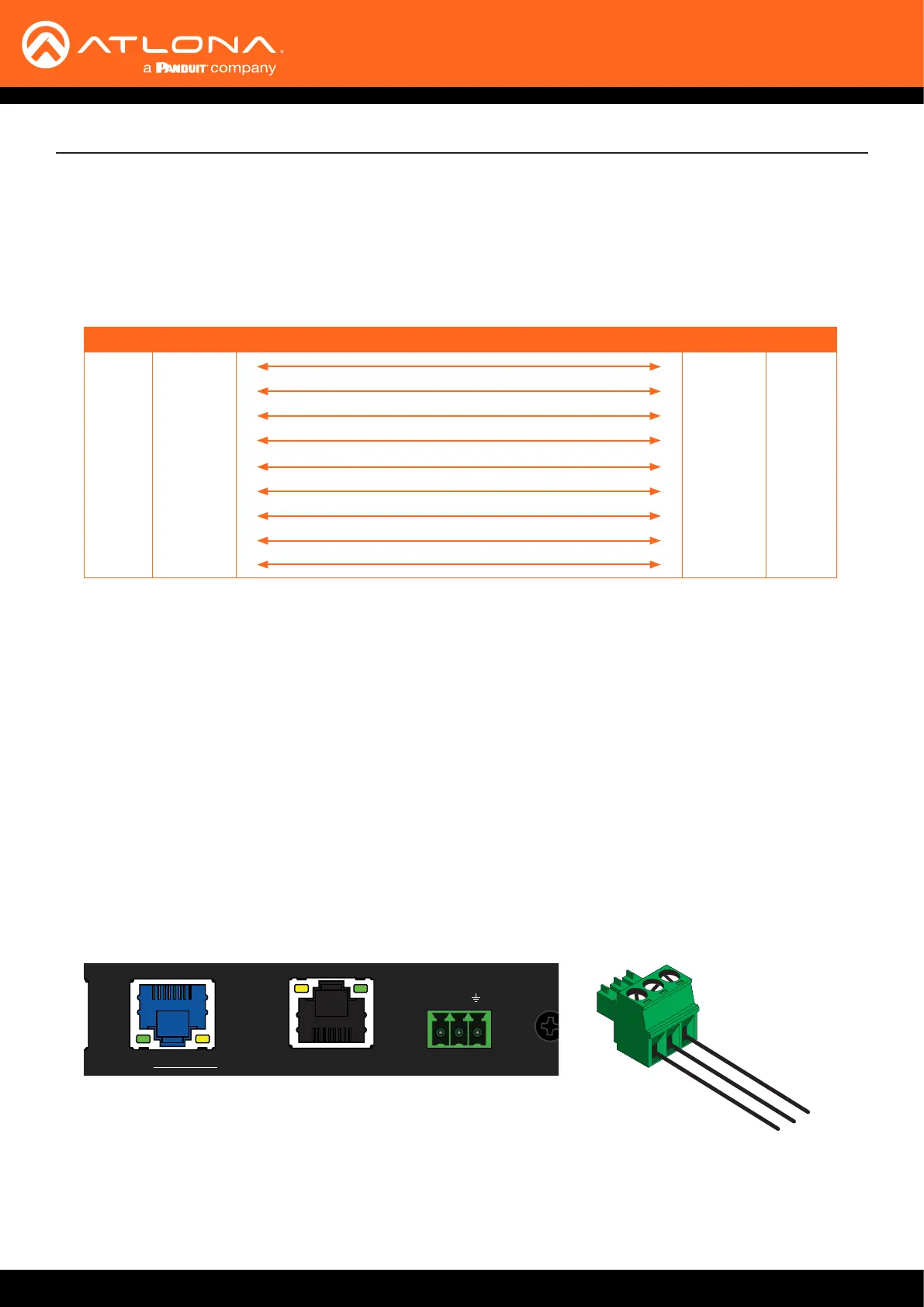
When connecting a DTE device to a DCE device, a straight-through cable should be used. A straight-through cable
is wired in such a way that the pins on one side of the cable are connected to the corresponding pins on the opposite
side of the cable, as shown in the table below. However, the AT-UHD-CLSO-840 will use only TxD, RxD, and GND
signals when communicating with a control system or computer.
Pin Signal Signal Pin
1 DCD DCD 1
2 RxD TxD 2
3 TxD RxD 3
4 DTR DSR 4
5 GND GND 5
6 DSR DTR 6
7 RTS CTS 7
8 CTS RTS 8
9 RI RI 9
Straight-Through Cable
HDMI IN HDBaseT IN
R L
1
R L
2
76 8
21 3 4
4321 5
R L
3
R L
4
R L
1
R L
2
R L
3
R L
4
HDBaseT OUT
LAN
ON
OFF
PWR 100-240VAC 50/60Hz
RS-232
HDMI OUT
AUDIO IN AUDIO OUT
+ + + + + ++ + + + + + + ++ +
RX TX
AT-UHD-CLSO-840
FCN CANCEL EDID
INFO
POWER ENTER 5 6 7 8
1 2 3 4
GND
RxD
TxD
10. Locate the included 3-pin captive screw block and open each of the terminals by
turning the screws counter-clockwise, using a small regular screwdriver.
11. Insert the TxD, RxD, and GND wires into correct terminal, as shown, and tighten the
screws to secure each wire. Do no overtighten.
12. Connect the captive screw connector to the RS-232 port on the AT-UHD-CLSO-840.
Bekijk gratis de handleiding van Atlona AT-UHD-CLSO-840, stel vragen en lees de antwoorden op veelvoorkomende problemen, of gebruik onze assistent om sneller informatie in de handleiding te vinden of uitleg te krijgen over specifieke functies.
Productinformatie
| Merk | Atlona |
| Model | AT-UHD-CLSO-840 |
| Categorie | Niet gecategoriseerd |
| Taal | Nederlands |
| Grootte | 11442 MB |


