Advantech PCM-3718H handleiding
Handleiding
Je bekijkt pagina 26 van 80
PCM-3718 Series User Manual 18
2.3 Connector Pin Assignments
PCM-3718 cards have two onboard 20-pin flat-cable connectors (insula-
tion displacement, mass termination).
The figure on page 5 shows locations of both connectors, while the next
page shows pin assignments for P1, P2 and P3.
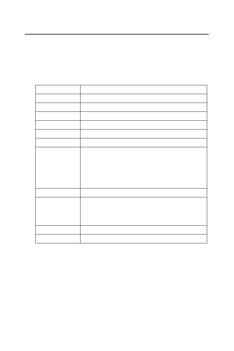
Refer to the table below for descriptions for abbreviations on the pins.
Abbreviations Description
A/D S Analog input (single-ended)
A/D H Analog input high (differential)
A/D L Analog input low (differential)
A.GND Analog ground
DIO Digital input/output
D.GND Digital and power supply ground
PCR_TRIG Pacer Clock Output. This pin pulses once for
each pacer clock when turned on. If A/D conver-
sion is in the pacer trigger mode, this signal can
be used as a synchronous signal for other appli-
cations. A low - to- high edge triggers A/D con-
version to start.
CNT0_Gate Counter 0 Gate
EXT_TRIG A/D External Tirgger. This pin is external trigger
signal input for the A/D conversion. A low-to-
high edge triggers A/D conversion to get one
sample.
CNT0_OUT Counter 0 Output
CNT0_CLK Counter 0 Clock
Bekijk gratis de handleiding van Advantech PCM-3718H, stel vragen en lees de antwoorden op veelvoorkomende problemen, of gebruik onze assistent om sneller informatie in de handleiding te vinden of uitleg te krijgen over specifieke functies.
Productinformatie
| Merk | Advantech |
| Model | PCM-3718H |
| Categorie | Niet gecategoriseerd |
| Taal | Nederlands |
| Grootte | 5483 MB |


