Advantech PCL-730 handleiding
Handleiding
Je bekijkt pagina 4 van 4
4 Startup Manual
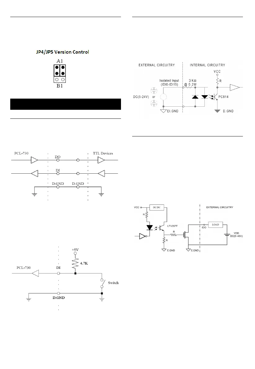
Version control (JP4/JP5)
Jumper JP4 controls the pin assignments for CN1 and
CN6 while JP5 controls it for CN2 and CN6. Setting
this jumper to A1 makes the card's pin assignments the
same as the A1 version.
TTL-level I/O
The PCL-730 has 16 TTL-level digital inputs and 16
TTL-level digital outputs. The following figure shows
connections to exchange digital signals with other TTL
devices:
If you want to receive an OPEN/SHORT signal from a
switch or relay, add a pull-up resistor to ensure that the
input is held at a high level when the contacts are open.
See the figure below:
Isolated Input
Each of the 16 isolated digital input channels accept
voltages from 5 to 24 V and have a resistance of 3 kΩ .
Every eight input channels share one external ground.
(Channels 0~7 use EI.GND1. Channels 8~15 use
EI.GND2.) The following figure shows how to connect
an external input source to the card's isolated inputs:
Isolated Output
Each of the 16 isolated digital output channels comes
equipped with a MOSFET. Every eight output channels
share common emitters and integral suppression diodes
for inductive load, activated by connecting PCOM to
VDD. (Channels 0~7 use PCOM1. Channels 8~15 use
PCOM2.)
If the external voltage (5~40 V) is connected to each
isolated output channel (IDO) and its isolated digital
output turns on (200 mA per channel maximum), the
card's current will sink from the external voltage.
Signal Connections
Bekijk gratis de handleiding van Advantech PCL-730, stel vragen en lees de antwoorden op veelvoorkomende problemen, of gebruik onze assistent om sneller informatie in de handleiding te vinden of uitleg te krijgen over specifieke functies.
Productinformatie
| Merk | Advantech |
| Model | PCL-730 |
| Categorie | Niet gecategoriseerd |
| Taal | Nederlands |
| Grootte | 689 MB |


