Advantech PCL-730 handleiding
Handleiding
Je bekijkt pagina 2 van 4
2 Startup Manual
6. Fasten the bracket of the PCL-730 card on the back
panel rail of the computer with screws.
7. Connect appropriate accessories (37-pin cable, wiring
terminals, etc. if necessary) to the PCL-730 card.
8. Replace the cover of your computer chassis. Re-con-
nect the cables you removed in step 2.
9. Plug in the power cord and turn on the computer.
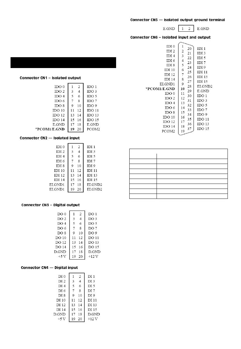
*NOTE: When JP4 is set to B1, Pin 19 on CN1 and Pin
10 on CN6 will both be assigned PCOM1. When JP4 is
set to A1, both pins will be assigned E.GND. For JP5,
Pin 17 & 19 and Pin 18 & 20 on CN2 will combine
together (be the same GND) when JP5 is set to A1. But
Pin 17 & 19 and Pin 18 & 20 on CN2 will be different
GND (EI.GND1 and EI.GND2 separately) when JP5 is
set to B1.
Pin Assignments
Abbreviations
DO Digital Output
DI Digital Input
IDO Isolated Digital Output
IDI Isolated Digital Input
E.GND External Ground for Isolated Output
EI.GND External Ground for Isolated Input
D. GND Digital Ground
VDD External Power for Isolated Outputs
PCOM Free Wheeling Common Diode
Bekijk gratis de handleiding van Advantech PCL-730, stel vragen en lees de antwoorden op veelvoorkomende problemen, of gebruik onze assistent om sneller informatie in de handleiding te vinden of uitleg te krijgen over specifieke functies.
Productinformatie
| Merk | Advantech |
| Model | PCL-730 |
| Categorie | Niet gecategoriseerd |
| Taal | Nederlands |
| Grootte | 689 MB |


