Advantech PCI-1742U handleiding
Handleiding
Je bekijkt pagina 26 van 58
PCI-1742U User Manual 20
Chapter 3 Signal Connections
3.1 I/O Connector
The I/O connector on the PCI-1742U is a 68-pin connector that enables
you to connect to accessories with the PCL-10168 shielded cable.
Fig. 3-1 shows the pin assignments for the 68-pin I/O connector on the
PCI-1742U, and table 3-1 shows the I/O connector signal description.
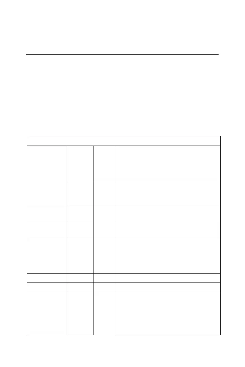
3.1.1 I/O Connector Signal Description
Table 3.1: I/O Connector Signal Description
AI<0…15> AIGND Input Analog Input Channels 0 through 15.
Each channel pair, AI<i, i+1> (i = 0, 2,
4...14), can be configured as either two
single-ended inputs or one differential
input.
AIGND - - Analog Input Ground. The three ground
references (AIGND, AOGND, and
DGND) are connected together.
AO0_REF
AO1_REF
AOGND Input Analog Output Channel 0/1 External Ref-
erence.
AO0_OUT
AO1_OUT
AOGND Output Analog Output Channels 0/1
AOGND - - Analog Output Ground. The analog out-
put voltages are referenced to these
nodes. The three ground references
(AIGND, AOGND, and DGND) are con-
nected together.
DI<0..15> DGND Input Digital Input channels.
DO<0..15> DGND Output Digital Output channels.
DGND - - Digital Ground. This pin supplies the ref-
erence for the digital channels at the I/O
connector as well as the +5VDC supply.
The three ground references (AIGND,
AOGND, and DGND) are connected
together.
Bekijk gratis de handleiding van Advantech PCI-1742U, stel vragen en lees de antwoorden op veelvoorkomende problemen, of gebruik onze assistent om sneller informatie in de handleiding te vinden of uitleg te krijgen over specifieke functies.
Productinformatie
| Merk | Advantech |
| Model | PCI-1742U |
| Categorie | Niet gecategoriseerd |
| Taal | Nederlands |
| Grootte | 5110 MB |


