Advantech PCI-1285 handleiding
Handleiding
Je bekijkt pagina 21 van 247
13 PCI-1285/1285E User Manual
Chapter 3 Signal Connections
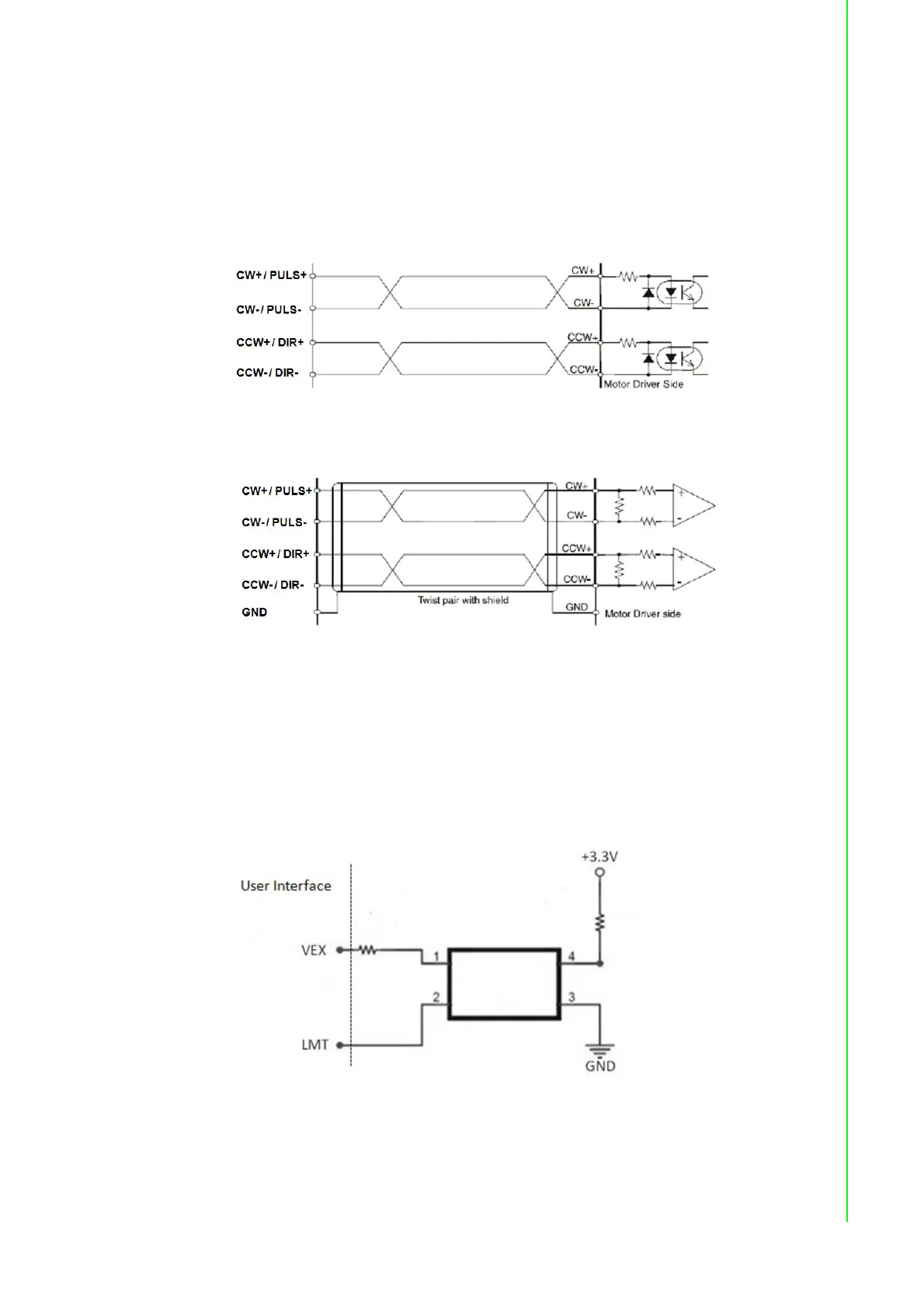
3.3 Output Pulse [CW± / PULS±,CCW± / DIR±]
The pulse command has two types: One is in clockwise/ counter- clockwise mode;
the other is in pulse/direction mode. CW+ / PULS+ and CW- / PULS- are differential
signal pairs and CCW+ / DIR+ and CCW- / DIR- are differential signal pairs. Default
setting of pulse output mode is pulse/direction. User can change the output mode by
programming.
Figure 3.4 Photocoupler Interface
Figure 3.5 Line Drive Interface
3.4 Over Traveling Limit Switch Input [ LMT+/- ]
Over traveling limit switches are used for system protection. This input signal is con-
nected through the connection of photo coupler and RC filter. When the limit switch is
applied, the external power VEX DC 12 ~ 24 V will be the source of the photo cou-
pler. This enables the over traveling function.
Figure 3.6 Circuit Diagram for Limit Input Signals
Bekijk gratis de handleiding van Advantech PCI-1285, stel vragen en lees de antwoorden op veelvoorkomende problemen, of gebruik onze assistent om sneller informatie in de handleiding te vinden of uitleg te krijgen over specifieke functies.
Productinformatie
| Merk | Advantech |
| Model | PCI-1285 |
| Categorie | Niet gecategoriseerd |
| Taal | Nederlands |
| Grootte | 31021 MB |


