Advantech MIC-75M20 handleiding
Handleiding
Je bekijkt pagina 2 van 12
2 MIC-75M20-00 Startup Manual
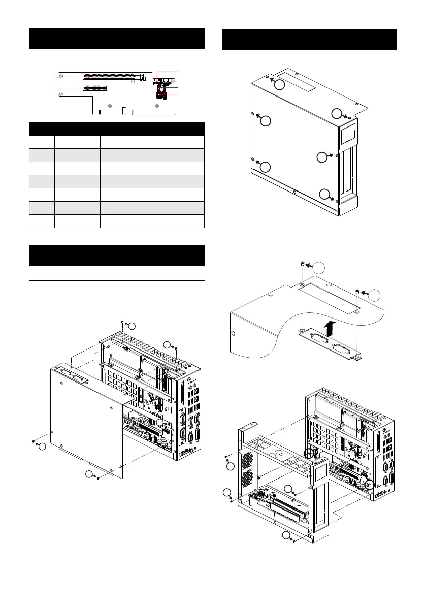
2. Undo the 6 screws on the MIC-75M20.
2
2
2
2
2
2
3. Remove the i-door cover on the system bottom and
assemble and secure the cover onto the i-module’s
bottom cover.
3
3
4. Align the MIC-75M20 and MIC-7 and secure 4 screws.
3
3
3
3
The table below lists the functions of each of the connectors.
PCIE p2-x4 Socket
PCIE p2-x16 Socket
12V Extra Power
FAN CON 1 & 2
Extra Power
5V Extra Power
Connectors
No. Item Function
1 SATAPWR1 4-pin Power connector (5V)
2 PWR2 4-pin Power connector (12V)
3 FAN 1 4-pin FAN connector
4 FAN 2 4-pin FAN connector
5 PCIEx4_1 PCIe p2-x4 socket
6 PCIEx16_1 PCIe p2-x16 socket
System Installation
The MIC-7 series i-module can be assembled with all MIC-7
series IPC systems.
1. Undo these screws on the MIC-7 series system and
remove the bottom cover.
1
1
1
1
2
Simple Maintenance Process
Jumpers and Connectors
Simple Maintenace Process (Cont.)
Bekijk gratis de handleiding van Advantech MIC-75M20, stel vragen en lees de antwoorden op veelvoorkomende problemen, of gebruik onze assistent om sneller informatie in de handleiding te vinden of uitleg te krijgen over specifieke functies.
Productinformatie
| Merk | Advantech |
| Model | MIC-75M20 |
| Categorie | Niet gecategoriseerd |
| Taal | Nederlands |
| Grootte | 2048 MB |


