Advantech iDAQ-821 handleiding
Handleiding
Je bekijkt pagina 25 van 36
15 iDAQ-817_821 User Manual
Chapter 3 Function Details
3.2.5 Analog Multiplexer
The analog multiplexer routes one of the analog input channels at a time (one for sin-
gle-ended configuration, and two for differential configuration) to the PGIA and ADC
to be measured. This mechanism is called channel scanning. It realizes multiple
channel measurement using only one ADC at a cost of sharing ADC sample rate
among all scanned channels.
User can select a range of channels to be scanned. The selected channels will be
scanned by the order of channel number. After the last channel is scanned, the next
channel will be the first channel. For example, if channels 3, 4, 5, 6, and 7 are
selected, the scanning sequence is channel 3, 4, 5, 6, 7, 3, 4, 5, 6, 7, 3, etc.
3.2.6 Analog Input Isolation
The analog input circuitry is equipped with a galvanic isolator, which can withstand a
large continuous voltage between external side and internal side. This prevents the
internal components and the host devices (e.g. PC) from damaging when such fault
condition happens.
3.3 Analog Output
Insert an iDAQ module supporting analog output function to perform analog output
update/generation. The following sections describe the analog output update/genera-
tion mechanism. They all apply to iDAQ-821.
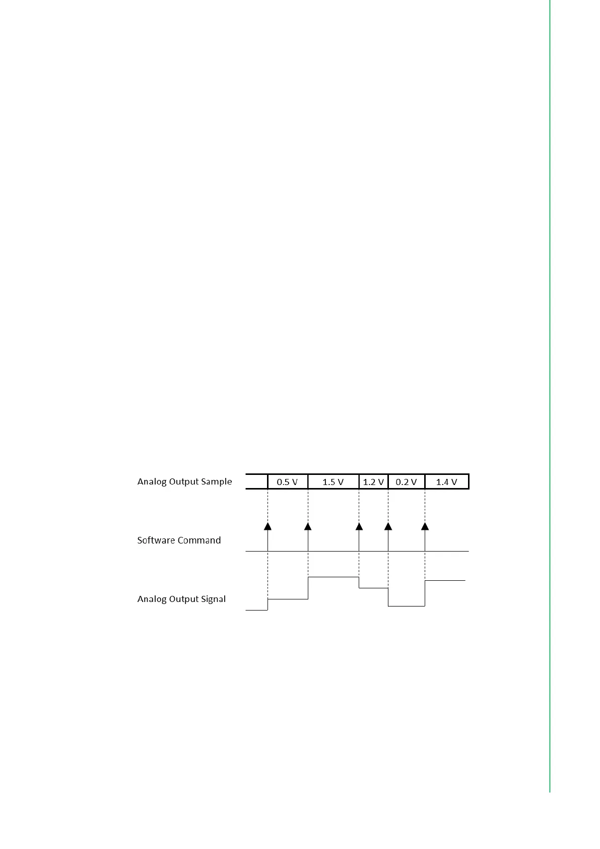
3.3.1 Static Analog Output Update
With static analog output update, the analog output voltage or current is updated only
when the software sends a “write static analog output sample” command. The analog
output voltage or current remains unchanged at other times. This is shown in Figure
3.6.
Figure 3.6 Static analog output update
3.3.2 Buffered Analog Output Waveform Generation
With buffered analog output waveform generation, the DAC conversion rate and the
duration of the generation is controlled by hardware timing signals. The analog output
waveform to be generated are first programmed and stored in the buffer memory in a
digital form. The digital values are converted to analog voltage or current one by one
for each sample clock as shown in Figure 3.7.
Bekijk gratis de handleiding van Advantech iDAQ-821, stel vragen en lees de antwoorden op veelvoorkomende problemen, of gebruik onze assistent om sneller informatie in de handleiding te vinden of uitleg te krijgen over specifieke functies.
Productinformatie
| Merk | Advantech |
| Model | iDAQ-821 |
| Categorie | Niet gecategoriseerd |
| Taal | Nederlands |
| Grootte | 2721 MB |


