AccuTemp Evolution N61201D060 handleiding
Handleiding
Je bekijkt pagina 14 van 28
Installation Manual I Installation
12
MP4010-1809
3.9 Connected Model - Additional Connections
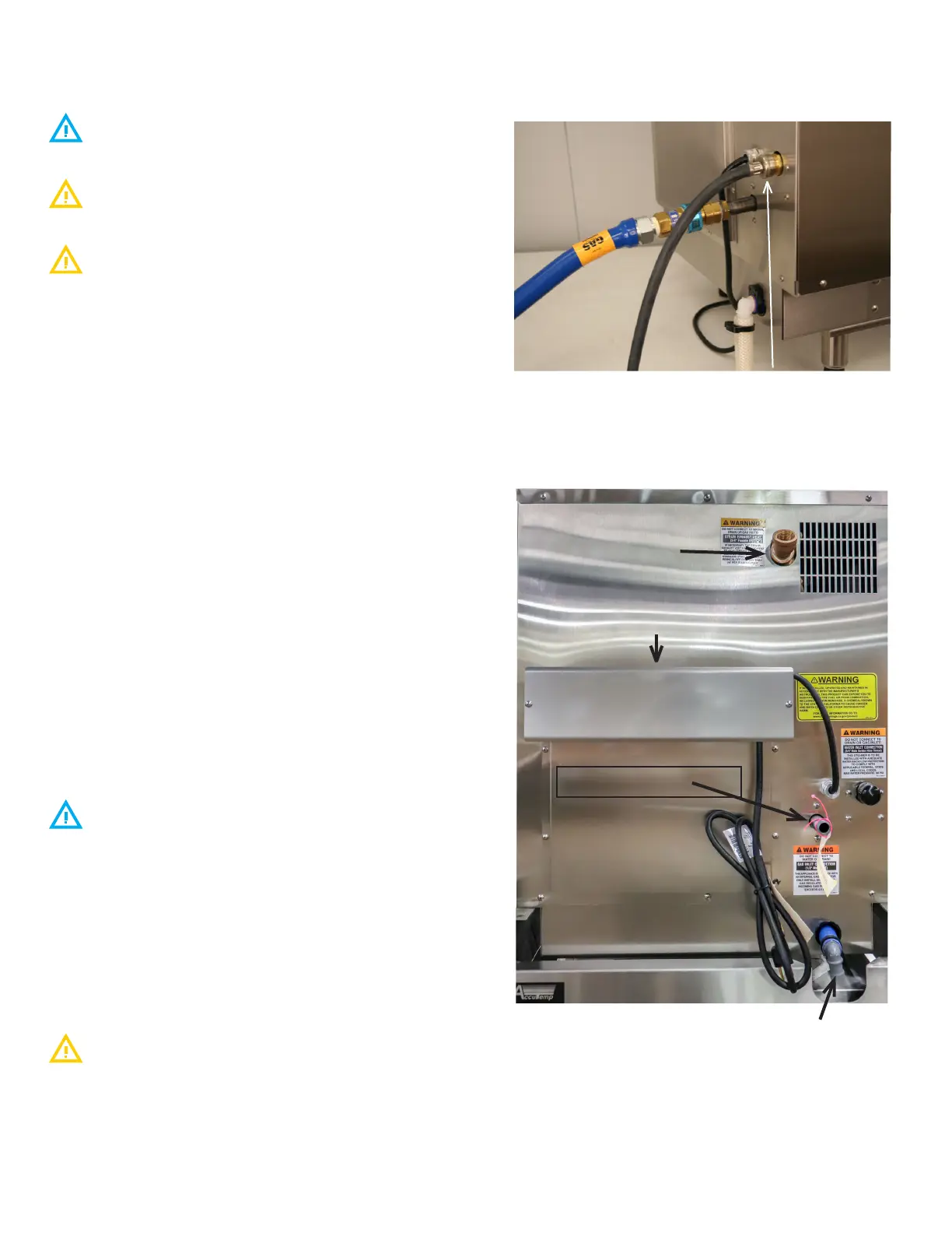
3.9.1 Supply Water Line (FIGURE 10)
The installation of the water connection to the appliance is
the responsibility of the owner and or installer.
The installation of this appliance should comply with all
applicable federal, state or local plumbing codes.
The installation requires a check valve (or other approved
anti-back flow/ anti-siphon device) in all supply lines in accor-
dance with and as required by local, state and national health,
sanitation and plumbing codes. AccuTemp does NOT provide a
check valve included with the steamer.
• Design the water supply line so the unit can be moved for
service. Install a manual water valve between the water
supply line and the steamer supply line.
• A reinforced rubber or braided stainless steel appliance
hose rated for the temperature and pressure of the
water supply with a 3/4” garden hose type connection is
required.
• The Garden Hose Thread (GHT) connector used must
be suitable for potable water
• Do not apply pipe thread sealant to GHT
connections.
• Install a manual water shut-o valve (not provided)
between the cold water supply line and the appliance.
• Either hot or cold water can be connected to the
steamer. If hot is used, temperature must be less
than 180°F.
• The hose must not be sharply bent, kinked or twisted.
• If the steamer is close to a wall, use a right angle fitting to
prevent kinking the hose
• Flush the water supply lines before connecting the lines to
the appliance.
• Connect the water supply lines to the steamer.
3.9.2 Drain Line Connection
Floor Drain
The steamer should be located close to, but not within
20” or directly over, a floor drain.
• Connect a ¾” ID reinforced rubber hose rated for 212°F
or higher to the drain fitting on rear of the steamer with a
hose clamp.
• Run the hose to the drain. DO NOT directly plumb the
steamer to the drain, Leave a one-inch air gap between the
hose and the drain.
• The hose must drop 1/4” (inch) per foot to the drain.
• Ensure no loops form in the drain line as this can cause a
backup and will aect the operation of the unit
The unit should not be located within 20” of a floor drain.
Optional Drain Connection
Run the hose to a funnel fitting leaving a one-inch gap between
the hose and the top of the funnel. The drain hose must slope
toward the floor drain or funnel.
FIGURE 10
WATER INLET
GAS CONNECTION
DRAIN CONNECTION
CONNECTED STEAMERS ONLY
STEAM EXHAUST VENT
DO NOT CONNECT TO GAS,
DRAIN OR WATER INLET
GAS EXHAUST FLUE
FIGURE 11
Bekijk gratis de handleiding van AccuTemp Evolution N61201D060, stel vragen en lees de antwoorden op veelvoorkomende problemen, of gebruik onze assistent om sneller informatie in de handleiding te vinden of uitleg te krijgen over specifieke functies.
Productinformatie
| Merk | AccuTemp |
| Model | Evolution N61201D060 |
| Categorie | Niet gecategoriseerd |
| Taal | Nederlands |
| Grootte | 9044 MB |


