Wago EPSITRON 787-1662 handleiding
Handleiding
Je bekijkt pagina 40 van 48
40 Function Description EPSITRON®
787-1662 Electronic Circuit Breaker
Manual
Version 1.0.0
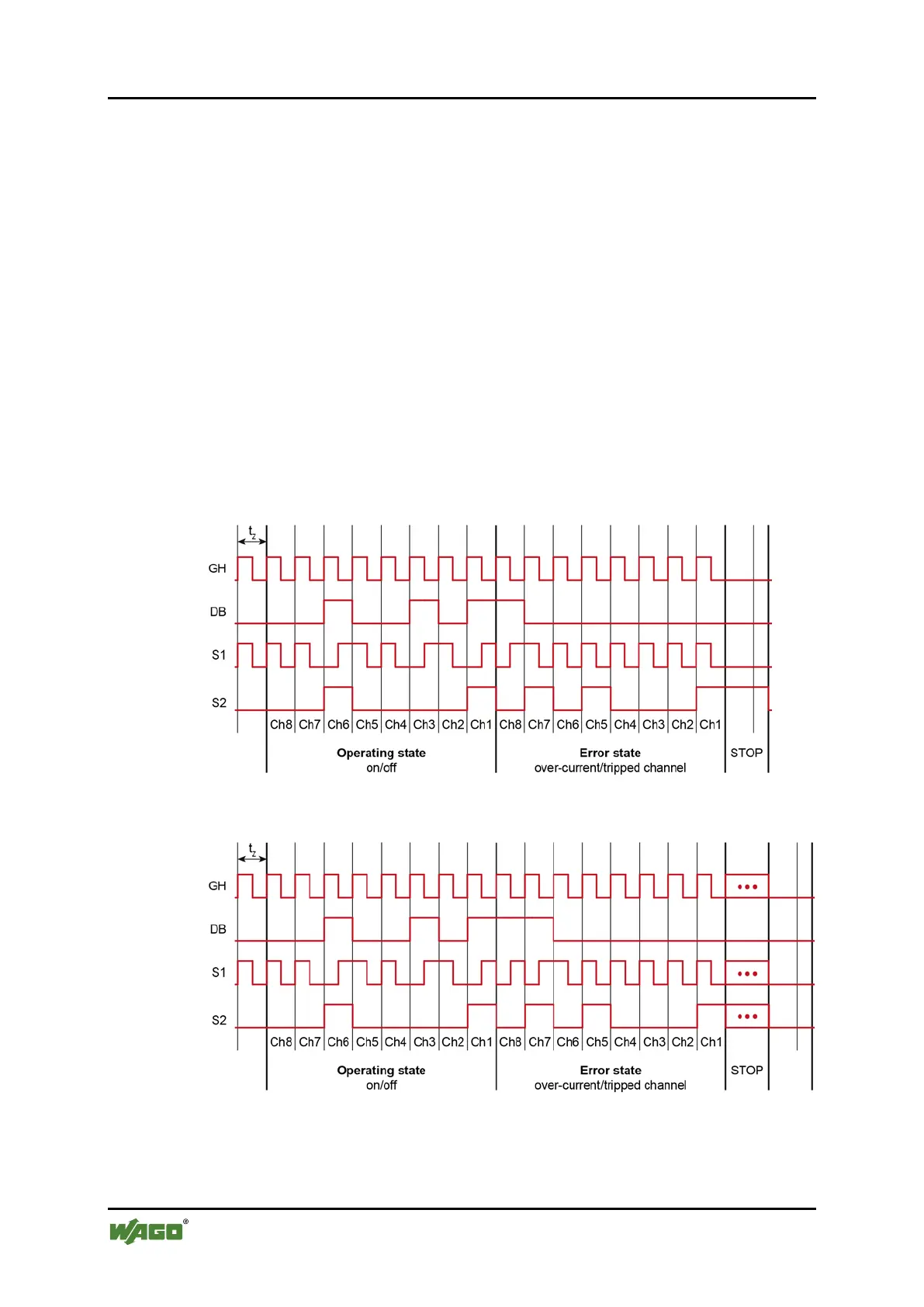
Changing of the signal voltage from 15 V … 30 VDC to 0 V … 5 VDC (falling
clock pulse) corresponds to a logical zero ("0").
Changing of the signal voltage from 0 V … 5 VDC to 15 V … 30 VDC (rising
clock pulse) corresponds to a logical one ("1").
The minimum pulse period is 70 ms, the maximum 200 ms.
A jitter of ±5 % or ±5 ms is acceptable, with the higher value applying.
STOP Bit: The STOP bit uses 1.5 pulse cycles. During this time, the PLC may not
transmit any further bit.
Once the pulse pattern has been transmitted, S1 and S2 are returned to Low. A
new pulse pattern cannot be transmitted until after a period of 200 ms.
The coded pulse pattern must be generated in the PLC via an XOR link from an
auxiliary clock pulse and the data bits. This is illustrated by the examples in the
figures below:
Figure 19: Standard 17-bit protocol
Figure 20: Extended 89-bit protocol
Bekijk gratis de handleiding van Wago EPSITRON 787-1662, stel vragen en lees de antwoorden op veelvoorkomende problemen, of gebruik onze assistent om sneller informatie in de handleiding te vinden of uitleg te krijgen over specifieke functies.
Productinformatie
| Merk | Wago |
| Model | EPSITRON 787-1662 |
| Categorie | Niet gecategoriseerd |
| Taal | Nederlands |
| Grootte | 7325 MB |