Vulcan C24EO3AF handleiding
Handleiding
Je bekijkt pagina 23 van 43
Apply two to three wraps of electrical tape on valve
where the hose clamp seats during installation to help
prevent leaks.
Fig. 53
Verify cap and clamp are installed on outlet port not
being used.
WATER LEVEL ALARM
Disconnect the electrical power to
the machine and follow lockout /
tagout procedures.
1. Shut off electric and water supply.
2. Remove RIGHT SIDE PANEL.
3. Remove knurled knob (1, Fig. 54).
Fig. 54
4. Note and disconnect wiring (2, Fig. 54).
Take care not bend capillary tube (3, Fig. 54).
5. Reverse procedure to install.
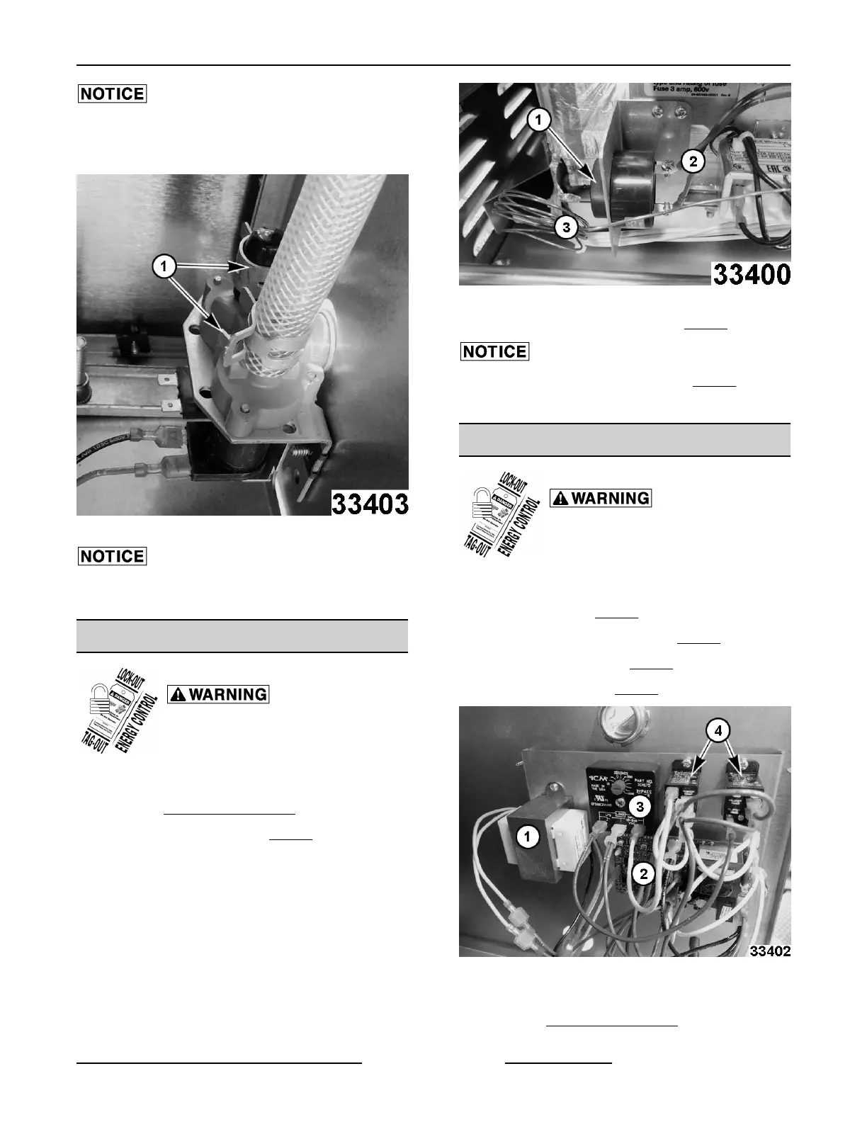
AUTOFILL CONTROL ASSEMBLY
Disconnect the electrical power to
the machine and follow lockout /
tagout procedures.
Components on the Autofill control assembly are:
• Transformer. (1, Fig. 55)
• Low Water Control Board. (2, Fig. 55)
• Time Delay Relay. (3, Fig. 55)
• Relay Switches. (4, Fig. 55)
Fig. 55
1. Shut off electric and water supply.
2. Remove RIGHT SIDE PANEL.
C24EO SERIES ELECTRIC COUNTERTOP STEAMERS - REMOVAL AND REPLACEMENT (AUTOFILL
OPTIONAL)
Page 23 of 43 F25386 Rev. C (0421)
Bekijk gratis de handleiding van Vulcan C24EO3AF, stel vragen en lees de antwoorden op veelvoorkomende problemen, of gebruik onze assistent om sneller informatie in de handleiding te vinden of uitleg te krijgen over specifieke functies.
Productinformatie
| Merk | Vulcan |
| Model | C24EO3AF |
| Categorie | Niet gecategoriseerd |
| Taal | Nederlands |
| Grootte | 15986 MB |


