Vestil RR-68-20 handleiding
Handleiding
Je bekijkt pagina 11 van 25
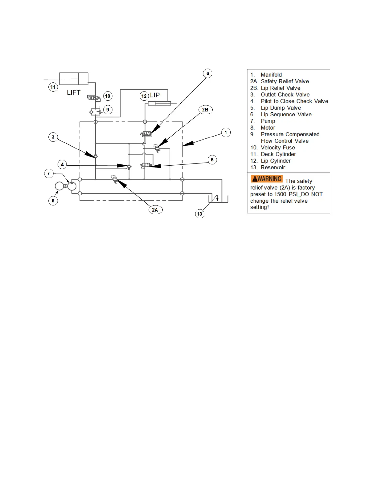
Table of Contents 7/2/2019 RR MANUAL
Table of Contents Copyright 2019 Vestil Manufacturing Corp. Page 11 of 25
Electrical system operation, EH Series
The electric circuit consists of a push-and-hold motor start circuit with thermal protection. The timer circuit
activates and runs the motor for approximately 10 seconds. The timer is actuated by either a limit switch in
automatic mode, or by pressing the RESET button in manual mode.
Hydraulic Circuit Sequence of Operation, EH Series [Numbers in Parentheses () Correspond to Numbers in
the Diagram Above]
EH-series dock levelers are hydraulically powered through a sequence of steps. The pressure required to raise
the deck varies with deck size. However, the pressure always remains below the pressure setting of the lip
sequence valve (6). The sequence valve is factory set to 700 PSI, unless the deck’s weight requires a different
setting, and should not be changed.
Pressing the “RAISE” button activates the pump. Oil pressure increases until it equals the cracking pressure of
the outlet check valve (3). The pressure closes valve (4), a pilot-to-close check valve with a 3:1 ratio. When the pilot
pressure exceeds one third of the inlet pressure, the valve closes. As pressure builds in the deck cylinder, the deck
rises and the lip rotates outward. When the pressure exceeds 40 PSI, the lip’s dump valve, (5), closes. The dump
valve is a normally open “pilot-to-close” directional valve.
As the lip rotates outward, oil from the cap end of the lip cylinder (12) is forced across the lip relief valve (2B).
The pressure setting of the lip relief valve divides oil flow between the deck cylinder (11) and the lip cylinder (12),
and controls the lip’s movement. If the pressure is too low, the lip will not fully extend. If pressure is too high, the lip
will retract too slowly and fail to return to its stowed position. The lip should completely rotate outward when the
deck rises approximately 18 inches.
After the deck cylinder fully extends, hydraulic pressure continues to increase until the lip sequence valve (6)
shifts. When the valve shifts, there is pressure on both sides of the lip cylinder. Because there is more pressure
applied to the cap end of the cylinder than to the rod end, the lip cylinder retracts.
Releasing the RAISE button deactivates the pump and the hydraulic pressure declines. When the pump output
pressure drops below one third of the lift pressure, the pilot-to-close check valve (4) opens and the deck begins to
descend. A pressure-compensated flow control valve (9) controls the deck’s rate of descent. Pressure continues to
decrease after the deck returns to its fully lowered position. When the pressure drops below 40 PSI, the lip dump
valve (5) opens which allows the lip to return to its stowed position.
The hydraulic system includes a safety device, called a velocity fuse, which prevents the deck from collapsing if
system pressure suddenly drops (for example, if the flow control valve fails or a hose is punctured). The fuse is
integrated into the cylinder. When the fuse closes oil cannot flow back to the reservoir.
Figure 4: Hydraulic circuit
Bekijk gratis de handleiding van Vestil RR-68-20, stel vragen en lees de antwoorden op veelvoorkomende problemen, of gebruik onze assistent om sneller informatie in de handleiding te vinden of uitleg te krijgen over specifieke functies.
Productinformatie
| Merk | Vestil |
| Model | RR-68-20 |
| Categorie | Niet gecategoriseerd |
| Taal | Nederlands |
| Grootte | 5984 MB |


