Vestil HLD-94-15-S handleiding
Handleiding
Je bekijkt pagina 8 van 19
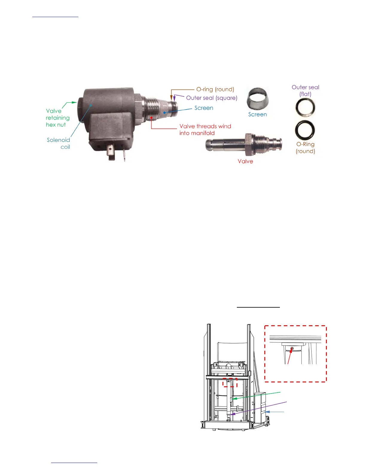
Table of Contents 2/4/2022 HLD MANUAL
Table of Contents Copyright 2010 Vestil Manufacturing Corp. Page 8 of 19
2. Disconnect electrical power to the equipment.
3. If loaded, remove the load from the chute.
4. For either the tilt cylinder (99-021-909-01) or the lift cylinder (99-021-912-001 or 99-021-913-001), remove the
valve retaining nut that fastens the solenoid coil to the valve stem, and then unscrew the valve from the
manifold.
NOTE: The end of the valve threads into the manifold and therefore will not be visible until the valve is
unwound from the manifold.
5. Inspect the outside of the valve. Look for debris inside of the valve cavity in the manifold. Replace the
valve if the valve stem is bent.
6. Inspect the O-ring and the outer seal for cuts, tears etc.
7. If necessary, remove debris from the valve:
a. Use a small screwdriver to press on the end of the valve. Insert the screwdriver into the valve. A
poppet inside the valve is normally closed by light spring tension. If the poppet is clear, it will move
approximately 1/16 in. when pressed. Use compressed air or canned air to blow through the valve while
pressing the poppet open. Mineral-spirits or kerosene can also be used to flush debris out of the valve.
b. If the poppet cannot move when pressed, the valve might be damaged. Replace the valve if the
poppet cannot move.
NOTE: Some models include a flow control spool inside the lowering valve cavity of the manifold. It is visible
once the valve is removed. The outer body of the lowering valve is threaded into the cavity; the inner
part of the spool has a spring behind it and can move under gentle pressure. Use a small standard
head screwdriver to gently press on the flow control spool to determine if it can move up and down.
If the spool does not move, the spring or the entire spool must be replaced.
c. Reinstall the screen, followed by the O-ring and then the outer seal.
8. Reinstall the valve in the manifold. Tighten the valve to 20 ft∙lb of torque.
REMOVING AIR FROM THE HYDRAULIC SYSTEM
Air is likely trapped inside the tilt cylinder or lift cylinder If the chute tilts very slowly when pressing the
LOWER TILT button or if it rises slowly while pressing the LOWER LIFT button. Air trapped in a cylinder causes its
velocity fuse to close. This prevents oil from flowing out of the cylinder.
• Put the chute in HOME position, i.e. lower the chute.
• Unload the chute.
• Find the bleeder valve located at the top of the
appropriate (lift or tilt) cylinder: 1) Part no. 99-021-909-
001 if the chute un-tilts slowly; 2) part no. 99-021-912-001
or 99-021-913-001 if the chute assembly descends
slowly. Hold a rag over the valve and open it about 1/2
turn with a 3/8” or 5/16” wrench. Oil and air will sputter
from the valve. Jog the motor by pressing the
appropriate control button (RAISE TILT or RAISE LIFT) for
just a second. If air continues to escape from the
bleeder valve, jog the motor several more times. Wait
at least 5 seconds between successive jogs.
• When air is no longer observed and only a clear stream
of oil flows from the bleeder valve, close the valve.
• Check the oil level in the reservoir. If the surface of the oil is more than 1 to 1½ in. below the fill hole, add
oil until it is between 1 and 1½ inches of the fill hole.
LOWERING SOLENOID CARTRIDGE VALVE ASSEMBLY
Bleeder valve of
lifting cylinder
Oil reservoir
located inside
power unit.
Tilt cylinder
Lift cylinder
Bekijk gratis de handleiding van Vestil HLD-94-15-S, stel vragen en lees de antwoorden op veelvoorkomende problemen, of gebruik onze assistent om sneller informatie in de handleiding te vinden of uitleg te krijgen over specifieke functies.
Productinformatie
| Merk | Vestil |
| Model | HLD-94-15-S |
| Categorie | Niet gecategoriseerd |
| Taal | Nederlands |
| Grootte | 5109 MB |


