Vestil EH-65-40 handleiding
Handleiding
Je bekijkt pagina 13 van 19
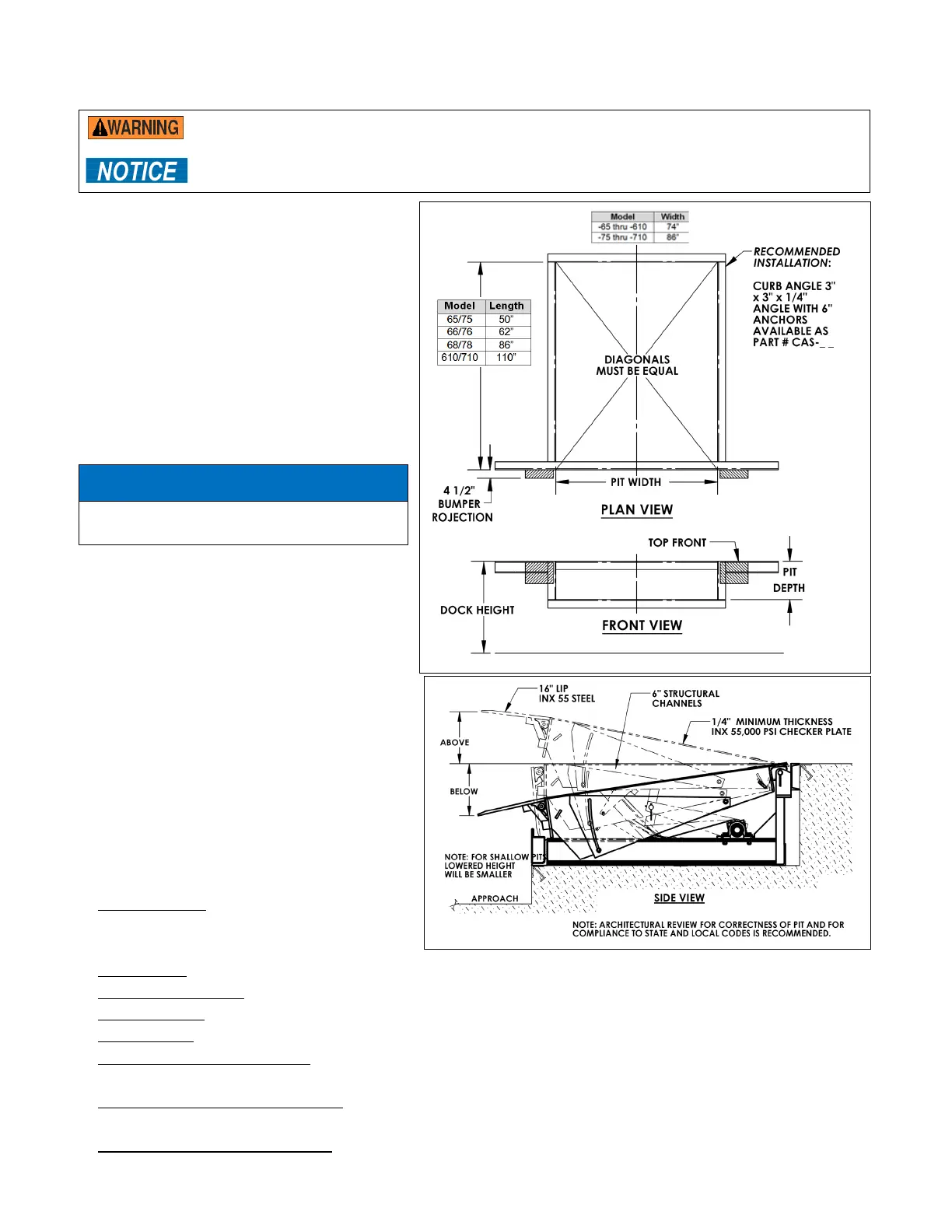
TABLE OF CONTENTS 5/12/2022 EH MANUAL
TABLE OF CONTENTS Copyright 2022 Vestil Manufacturing Page 13 of 19
INSTALLATION
Never work under a dock leveler unless the maintenance prop is installed in its socket.
The Dock Leveler must be level to function properly.
Do not modify the dock leveler to fit in a pit.
1. Measure the pit’s dimensions.
2. Using steel shims, position shims under the
frame to prevent frame distortions and flex
so the Dock Leveler’s final, resting position
meets the following:
• The Dock Leveler should be level.
• The Dock Leveler should be against the
rear pit curb angle.
• The platform should be centered from
side to side within the pit.
• The Dock Leveler’s rear channel must be
flush with the rear curb angle.
Do not allow the Dock Leveler to be
above the pit’s rear curb angle.
3. With the shims in position, skip weld the
rear hinge channel to the rear curb angel, 4
inches every 8 inches.
4. Grind welds smooth.
Operating the Dock Leveler
The Dock Leveler has an electric motor
directly coupled to a gear-type hydraulic
pump to pressurize the hydraulic system.
Hydraulic pressure allows the cylinders to lift
the platform and extend the lip. The
hydraulic control components are housed
within a manifold bolted directly onto the
gear pump. All hydraulic components are
rated for 3,000 psi working pressure.
Power unit parts include:
1. Electric motor: The A/C motor operates
on either single-phase or 3-phase AC,
depending on the motor ordered.
2. Gear pump: The pump shaft is coupled directly to the electric motor shaft.
3. Pressure relief valve: At pressures greater than 1,500 psi, fluid flows back into the reservoir.
4. Lip relief valve: The adjustable valve controls the Lip’s retract rate after the platform has risen.
5. Check valve: It prevents fluid backflow through the pump.
6. Pilot-operated check valve: This valve is closed while the leveler rises and it opens when the pilot
pressure drops to less than 1/3 of the inlet pressure, causing the deck to descend.
7. Pilot-to-close, two-position valve: Normally open, this valve closes when the pilot pressure exceeds 40
psi. It holds the lip in the extended position until either the platform or the lip is physically supported.
8. Pilot-operated sequence valve: When system pressure is ~700 psi, the valve shifts to extend the lip.
NOTE:
Pit bottom
should slope
¼ in. from
back to front.
The re
ar wall
(pit depth)
should be
23
3
/
4
in. Front
face pit
depth should
be 24”.
NOTICE
Bekijk gratis de handleiding van Vestil EH-65-40, stel vragen en lees de antwoorden op veelvoorkomende problemen, of gebruik onze assistent om sneller informatie in de handleiding te vinden of uitleg te krijgen over specifieke functies.
Productinformatie
| Merk | Vestil |
| Model | EH-65-40 |
| Categorie | Niet gecategoriseerd |
| Taal | Nederlands |
| Grootte | 4662 MB |


