Handleiding
Je bekijkt pagina 22 van 52
22
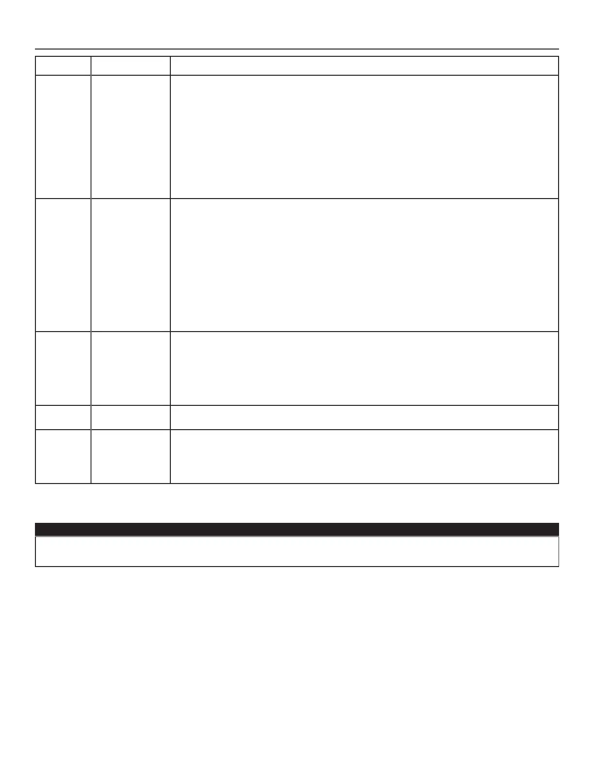
warning deScription Solution
W22
Supply airow
STEP 1: Unplug the unit. Perform a visual inspection of the supply damper system. Clean
lters, distribution registers and outside supply hood. Inspect ducting to ensure it is not
squeezed or bent. Plug the unit.
If STEP 1 did not x the problem, perform STEP 2: Remove ducting of the supply path. On the
LCD screen, select MAX to check if the unit is able to reach the selected ow. If so, review the
ducting path.
If STEP 2 did not x the problem, perform STEP 3: On the LCD screen, select the MIN and
MAX ow setting values then reset the unit. MAX ow value will display on the LCD screen. If
MAX ow is above desired MAX ow, set MAX and MIN ows.
If STEP 3 did not x the problem, perform STEP 4: Replace the supply blower and repeat
STEP 3.
If STEP 4 did not x the problem, perform STEP 5: Replace the electronic assembly.
W32
Exhaust airow
STEP 1: Unplug the unit. Perform a visual inspection of the exhaust damper system. Clean
lters, distribution registers and outside exhaust hood. Make sure no non-return damper
is installed in exhaust hood since it can freeze in winter. Inspect ducting to ensure it is not
squeezed or bent. Plug the unit.
If STEP 1 did not x the problem, perform STEP 2: Remove ducting of the supply path. On the
LCD screen, select MAX to check if the unit is able to reach the selected ow. If so, review the
ducting path.
If STEP 2 did not x the problem, perform STEP 3: On the LCD screen, select the MIN and
MAX ow setting values then reset the unit. MAX ow value will display on the LCD screen. If
MAX ow is above desired MAX ow, set MAX and MIN ows.
If STEP 3 did not x the problem, perform STEP 4: Replace the exhaust blower and repeat
STEP 3.
If STEP 4 did not x the problem, perform STEP 5: Replace the electronic assembly.
W40
Outside air
thermistor
The unit is still in operation, but preventive defrost cycles are added because outside air
thermistor is not properly read.
STEP 1: Check if thermistor is well connected in connector J7A.
If STEP 1 did not x the problem, perform STEP 2: Disconnect connector J7A and check if the
measured resistance (thermistor connector) is within 5 Kohms to 120 Kohms. If outside the
range, replace the thermistor.
If STEP 2 did not x the problem, perform STEP 3: Replace the electronic assembly.
W52
Initial setting
incomplete
STEP 1: Press + or - to access the selection menu.
STEP 2: Complete conguration. (Refer to section 5 for more details).
W61
Protection mode
electronics
overheating
The unit is currently in protection mode. The power transmitted to the motor is deliberately
reduced to decrease electronics temperature. The unit will exit this mode by itself once
conditions are back to normal. It is normal to observe reduction in airows during this period.
This condition should appear only when the unit is set in high speed and located in a warmer
environment, for example over 30°C (86°F).
8. INSTALLER’S TROUBLESHOOTING (cont’d)
Make sure that no piece of mineral wool will enter in the unit during installation. Otherwise, this could reduce
airow and generate vibrations and noise in the unit.
CAUTION
Bekijk gratis de handleiding van Venmar V130H80RT, stel vragen en lees de antwoorden op veelvoorkomende problemen, of gebruik onze assistent om sneller informatie in de handleiding te vinden of uitleg te krijgen over specifieke functies.
Productinformatie
| Merk | Venmar |
| Model | V130H80RT |
| Categorie | Airco |
| Taal | Nederlands |
| Grootte | 8526 MB |


