VARI-LITE VL800 Eventwash handleiding
Handleiding
Je bekijkt pagina 19 van 21
19
USER MANUAL
912400575012UM
WWW.VARI-LITE.COM
TABLE 6. DMX MAP - ALL
CHANNEL 16-BIT 1 CELL 16-BIT 7 CELL 8-BIT 1 CELL 8-BIT 7 CELL
65 Strobe Speed
66 Strobe Control
67 Focus Timing
68 Optics Timing
69 Color Timing
70 Control Channel
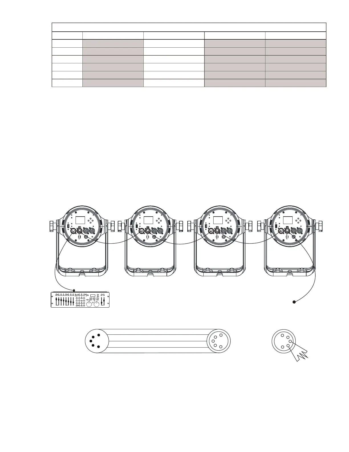
DMX512 CONNECTION
• At last unit, the DMX cable has to be terminated with a terminator. Solder a 120 1/4W resistor between
pin 2(DMX-) and pin 3(DMX+) into a 5-pin XLR-plug and plug it in the DMX-output of the last unit.
• Connect the unit together in a `daisy chain` by XLR plug from the output of the unit to the input of the
next unit. The cable can not branched or split to a `Y` cable. DMX 512 is a very high-speed signal. Inad-
equate or damaged cables, soldered joints or corroded connectors can easily distort the signal and shut
down the system.
• The DMX output and input connectors are pass-through to maintain the DMX circuit, when one of the
units’ power is disconnected.
• Each lighting unit needs to have an address set to receive the data sent by the controller. The address
number is between 0-511 (usually 0 & 1 are equal to 1).
• The end of the DMX 512 system should be terminated to reduce signal errors.
DMX CONTROLLER
DMX OUT
1
5
4
3
2
1
5
4
3
2
common
DMX-
DMX+
not used
not used
DMX output
DMX input
1
5
4
3
2
Bekijk gratis de handleiding van VARI-LITE VL800 Eventwash, stel vragen en lees de antwoorden op veelvoorkomende problemen, of gebruik onze assistent om sneller informatie in de handleiding te vinden of uitleg te krijgen over specifieke functies.
Productinformatie
| Merk | VARI-LITE |
| Model | VL800 Eventwash |
| Categorie | Niet gecategoriseerd |
| Taal | Nederlands |
| Grootte | 2663 MB |


