USL JSD-60 handleiding
Handleiding
Je bekijkt pagina 35 van 44
184050 Page 35
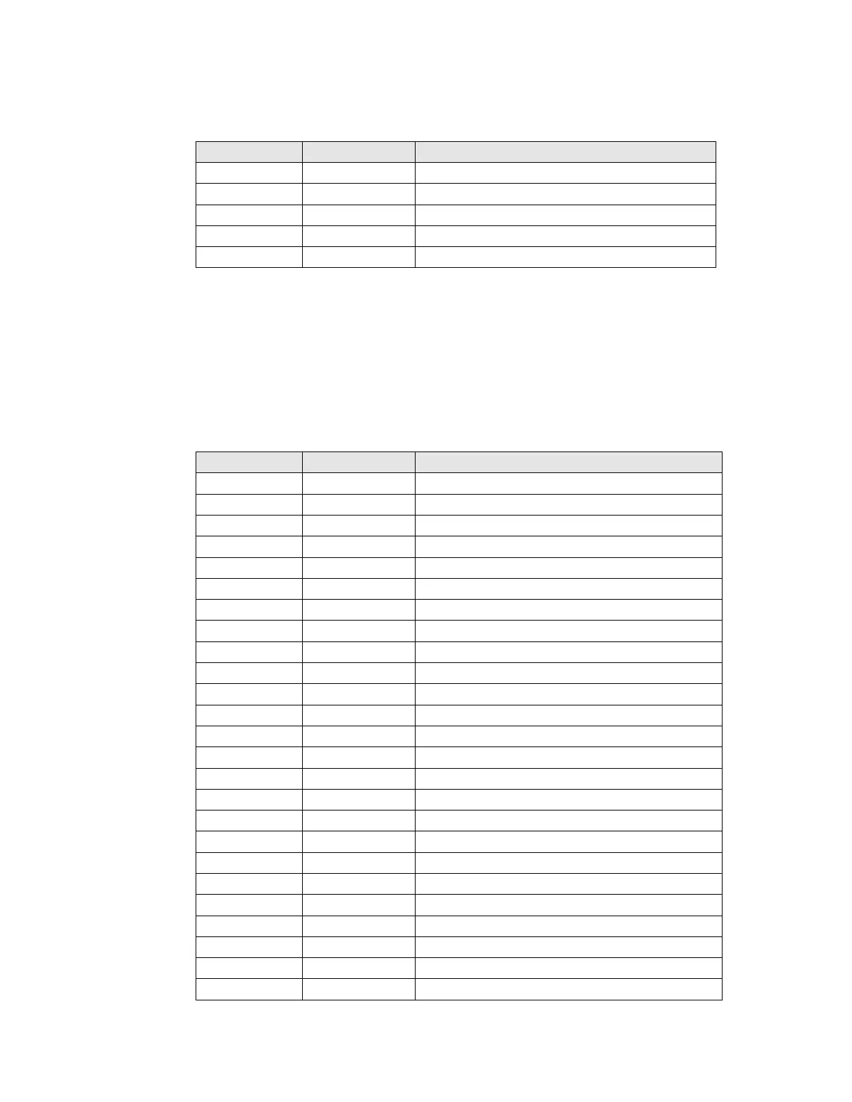
Signals Listed By Connector Pins
Phoenix Pin
Signal Name
Channel Name
1
HI+
Hearing Impaired+
2
HI-
Hearing Impaired -
3
GND
4
VI-N-
Visually Impaired – Narrative-
5
VI-N+
Visually Impaired – Narrative+
Parallel Automation Interface
Pins 1 through 7 of the DB25F automation connector are “control” pins that accept contact
closure or open collector pulses to ground to select formats. Pulsing pin 8 low toggles the mute
state. Pins 9 and 10 are used for remote fader operation. Each input sources up to 400 uA when
grounded. A pin needs to be pulled below 2.6 V for 50 ms or longer for the JSD-60 to recognize
it as low. On pin 13, a +5 V, 100 mA supply is available to power the JSDV-80 Remote Fader. An
automation return is on Pin 12.
DB25F Pin
Signal Name
Control Name
1
CTL1
COAX
2
CTL2
TOSLINK
3
CTL3
8 Channel Digital
4
CTL4
Option
5
CTL5
6 Channel Analog
6
CTL6
Non/Sync
7
CTL7
MIC
8
CTL8
System Mute
9
CTL9
Main Fader Up
10
CTL10
Main Fader Down
11
12
RTN
Automation Return
13
PWR
+5V at 100mA Power
14
15
16
17
18
19
20
21
22
23
24
25
Bekijk gratis de handleiding van USL JSD-60, stel vragen en lees de antwoorden op veelvoorkomende problemen, of gebruik onze assistent om sneller informatie in de handleiding te vinden of uitleg te krijgen over specifieke functies.
Productinformatie
| Merk | USL |
| Model | JSD-60 |
| Categorie | Niet gecategoriseerd |
| Taal | Nederlands |
| Grootte | 6052 MB |


