USL CM-8E handleiding
Handleiding
Je bekijkt pagina 30 van 40
30
Appendix A – Connector Pin Outs
Connector Pin Outs
For convenience, all connector pin outs are located in this appendix.
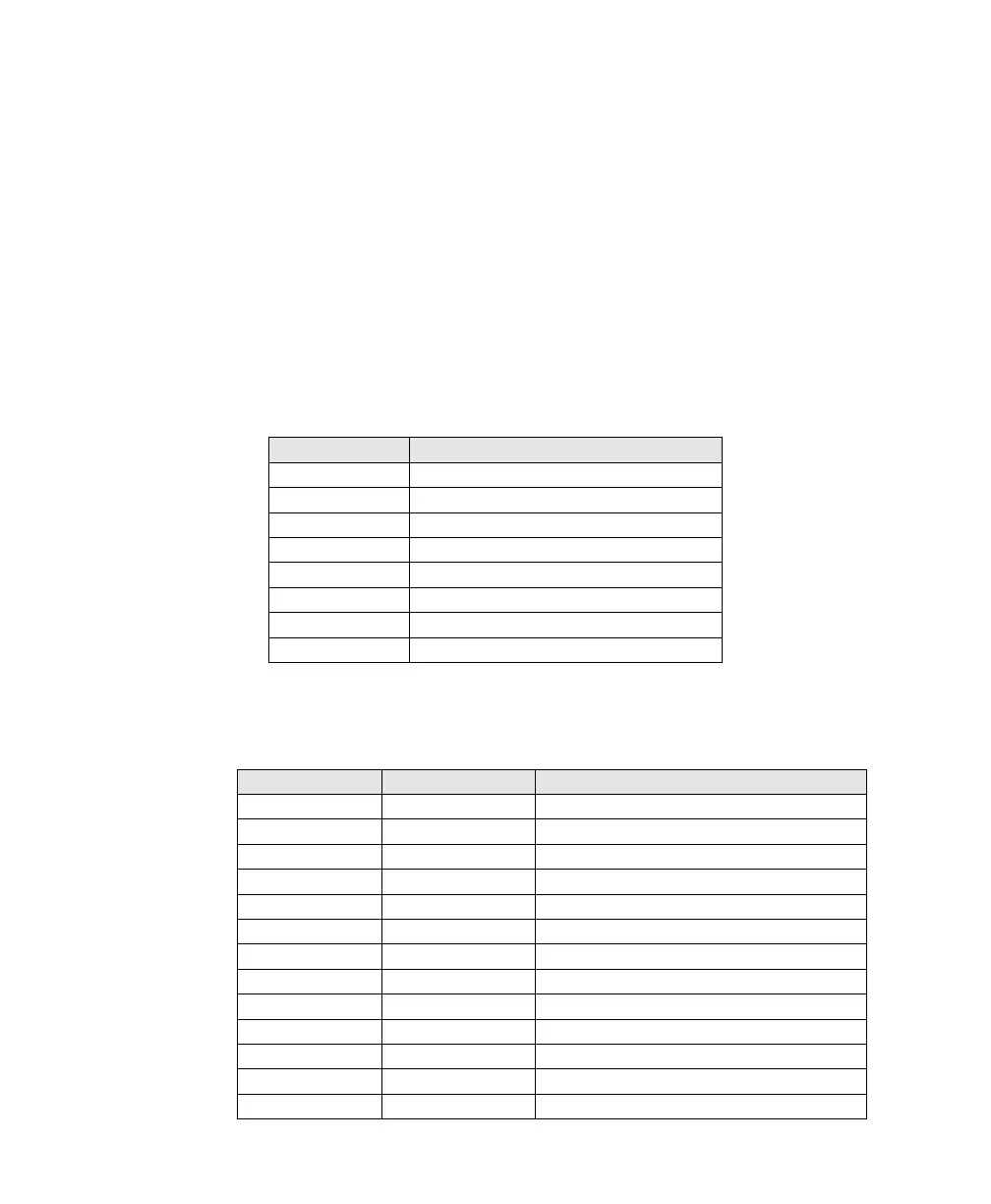
Main Inputs
The main inputs are on a DB-25F on the rear panel. These are full range on all channels if there
is no crossover in front of the CM-8E. They are the low band of the screen channels if there is a
crossover in front of the CM-8E (typically in the processor)
Main Inputs, Full Range and Crossover
Audio Channel
DB-25F Main Input Pins (+, -, shield)
Left
2, 14, 1
Center
5, 17, 4
Right
8, 20, 7
LFE
25, 12, 13
Ls
23, 10, 22
Rs
24, 11, 9
Lrs
16, 3, 15
Rrs
19, 6, 18
Signals Listed By Connector Pins
DB-25F Pin
Signal Name
Channel Name
1
GND
2
L+
Left+
3
Lrs-
Left Rear Surround-
4
GND
5
C+
Center+
6
Rrs-
Right Rear Surround-
7
GND
8
R+
Right+
9
GND
10
Ls-
Left Surround-
11
Rs-
Right Surround-
12
LFE-
Low Frequency Effects-
13
GND
Bekijk gratis de handleiding van USL CM-8E, stel vragen en lees de antwoorden op veelvoorkomende problemen, of gebruik onze assistent om sneller informatie in de handleiding te vinden of uitleg te krijgen over specifieke functies.
Productinformatie
| Merk | USL |
| Model | CM-8E |
| Categorie | Niet gecategoriseerd |
| Taal | Nederlands |
| Grootte | 5538 MB |


