Toa TS-D1100-MU handleiding
Handleiding
Je bekijkt pagina 9 van 52
9
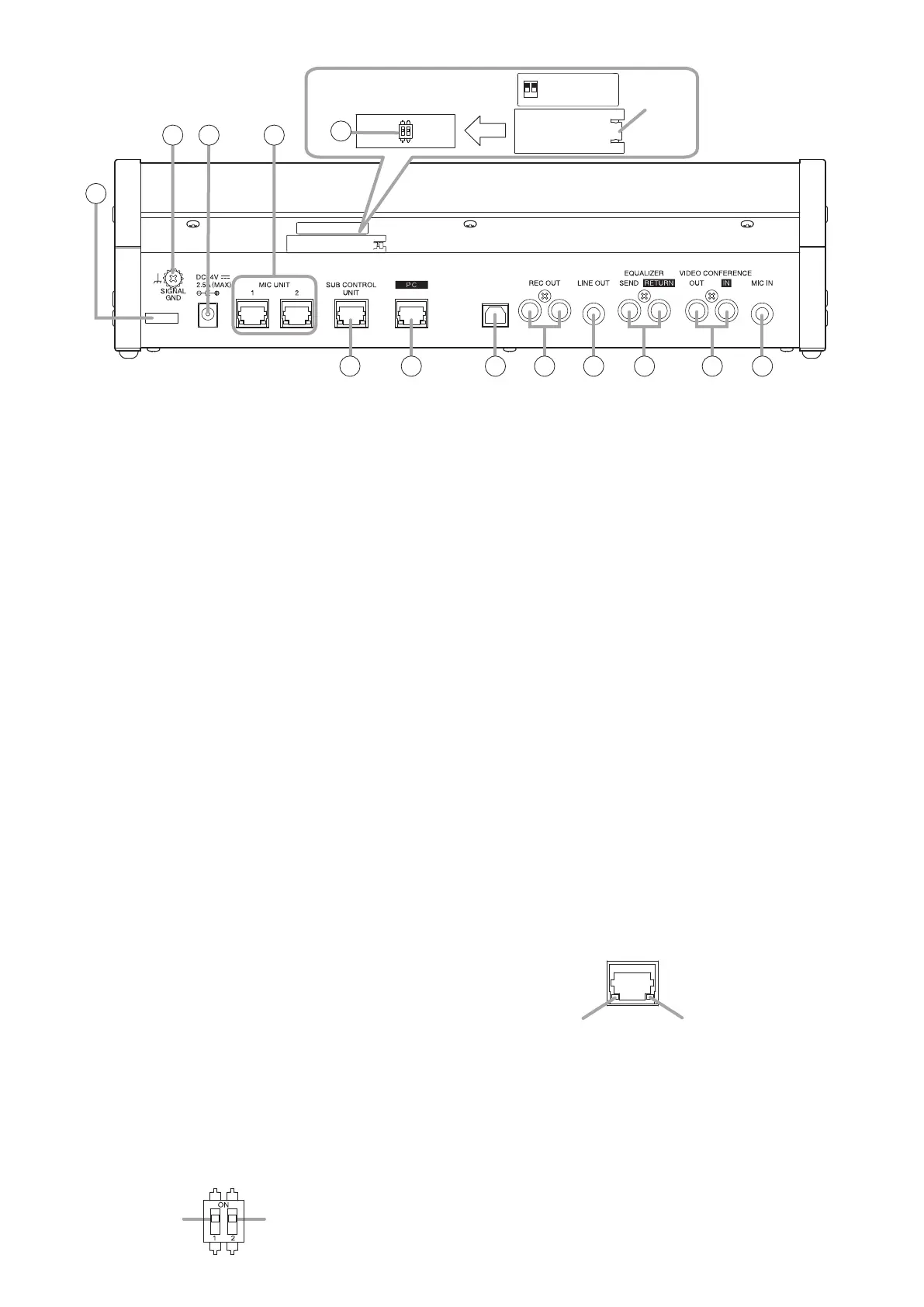
[Rear]
USB
28 29
30
27
(The figure which took off
the cover)
Cover
32 33 35
34 36
37
38 39
1:POWER SAVE
2:ID RESET
ON
OFF
1 2
ON
1 2
31
27. Cable clamp
Route the power cable through this clamp to
prevent the AC adapter plug from accidentally
being disconnected.
28. Signal ground terminal
When connection of an external device to the TS-
D1100-MU results in the generation of audible
noise, connect this terminal to the Signal ground
terminal of the external device. Noise output
should be greatly reduced.
Note
This is not a protective ground connection.
29. DC inlet
Insert the power plug from the unit’s supplied AC
adapter into this inlet.
30. Conference unit connection terminal
RJ45 x 2
Connects to the Conference unit by way of a
Cat5e STP LAN cable. Up to 16 conference units
can be daisy chain connected to each terminals.
However, there may be some restrictions on
the combinations of conference units that can
be connected to a single line. (See "SYSTEM
EXAMPLES" on p. 26.)
31. Function setting switch
Used to set both the Power Saving and ID Update
functions. (Factory default setting: ON)
Note
Be sure the power to the unit is rst turned OFF
before enabling or disabling this function. The
Power save ON/OFF setting cannot be modied
while the unit’s main power is switched ON, even
if manually operated.
If this switch is operated to enable or disable Power
save when the unit’s main power is switched ON,
the function is enabled or disabled after the main
power is once turned OFF and then turned back
ON again.
Switch 1 Switch 2
• Switch 1 [1: POWER SAVE]
Sets the Power saving function. Turning ON this
switch enables the Power saving function, and
turning it OFF disables the function.
Tip
If any device connected to the system, including
Conference units, is not operated for more
than two hours when this switch is set to ON,
power is automatically turned OFF. However,
when recording or speech operations are in
progress, the power turns o two hours after
such operations are terminated.
• Switch 2 [2: ID RESET]
Sets the ID reset function. Usually, this switch
is turned ON during use. Turn it OFF if the
conference unit’s ID is to be operated in a xed
manner during external control operations, etc.
32. Sub control unit connection terminal
RJ45
Connects to a maximum of 5 Sub-Control units by
way of a Cat5e STP LAN cable. If 5 Sub-Control
units are connected, up to 246 Conference units
can be connected to the system.
33. Network connection terminal
RJ45
Connects the PC to the network by way of a Cat5e
STP LAN cable.
LINK/ACT indicator
10BASE-T/
100BASE-TX indicator
• 10 BASE-T/100BASE-TX indicator (Orange)
Extinguishes when a 10BASE-T network is
connected to the TS-D1100-MU, and lights
when a 100BASE-TX network is connected.
• LINK/ACT indicator (Green)
Lights when the TS-D1100-MU is connected to
a network and ashes during data transmission/
reception.
Bekijk gratis de handleiding van Toa TS-D1100-MU, stel vragen en lees de antwoorden op veelvoorkomende problemen, of gebruik onze assistent om sneller informatie in de handleiding te vinden of uitleg te krijgen over specifieke functies.
Productinformatie
| Merk | Toa |
| Model | TS-D1100-MU |
| Categorie | Niet gecategoriseerd |
| Taal | Nederlands |
| Grootte | 5846 MB |


