Thames & Kosmos Robotics Workshop: Sensor Expansion Pack handleiding
Handleiding
Je bekijkt pagina 3 van 4
Robotics Workshop
3
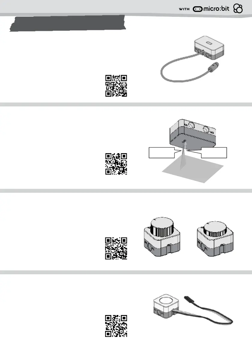
ROBOTIC COMPONENTS
Color sensor: The color of an object is determined by the
proportion of light colors reflected by the object. A color
sensor determines the color of an object by detecting the
reflected red (R), green (G), and blue (B) wavelengths of
light that are reflected by the object.
Scan the QR for help getting started
with the color sensor.
Infrared sensor: This kit includes two active infrared
sensors, which emit an infrared light. When obstructed
by an object, this light is reflected back to the sensor. The
receiver detects the reflected infrared light to determine if
there is an obstruction.
Scan the QR for help getting started
with the infrared sensor.
Toggle sensor: The toggle sensor functions similarly
to a button, transmitting a digital signal to the brain
(micro:bit) upon being pressed or released. It can
convey two types of signals to the brain: 1 or 0.
Scan the QR for help getting started
with the toggle sensor.
RGB LED: Also known as a multi-color light emitting
diode, this output device emits lights of various colors by
combining the primary colors of light: R (red), G (green),
and B (blue) in certain proportions.
Scan the QR for help getting started
with the RGB LED.
1cm~2cm
Principle of Infrared Sensors
- Infrared sensors primarily come in two types:
active and passive. Here we use an active infrared
sensor.
- Active infrared sensors emit an infrared light,
which, when obstructed by an object, reflects back.
The receiver detects the reflected infrared light to
determine if there is an obstruction.
1.
Detection Range
For optimal performance, it's recommended to
place the infrared sensor toward the surface or the
trigger object within the range of 1 to 2 cm for
emitting and receiving infrared light.
2.
Note:
The detection sensitivity has already been adjusted to optimal
settings, so there's no need to adjust it unless for special purposes.
emitted
infrared light
digital coding block
analog coding block
reflected
infrared light
Switching between Digital and Analog Signals
The sensor features a D/A switch on the back. Digital signals are commonly used, and all
models in this package utilize Digital mode for their applications.
3.
Adjustable Rotary Knob on the Back (for Digital Mode Only)
There is a hole on the back of the sensor, allowing adjustment of the sensitivity for detecting
Digital signals using a screwdriver.
4.
Infrared Sensor Introduction for Students
D (Digital) mode
programming involves distinguishing
between 0 and 1, representing presence
and absence, respectively.
A (Analog) mode
finer signal variations within the range of
0 to 1023 can be detected.
Note:
If you want to use Analog mode, please
only connect to analog channel, pin 1, 2, 0.
Principle of Toggle Sensor
- The toggle sensor functions similarly to a
button. transmitting a digital signal to the
brain (micro:bit) upon being pressed or
released. It can convey two types of signals to
the brain: 1 or 0.
- In the case of this toggle sensor, releasing it
sends a signal of 1, while pressing it sends a
signal of 0.
1.
Every time you release it, the status
becomes 1 again, and the LED
matrix will clear the screen.
Locking Mechanism of Toggle Sensor
This Toggle sensor is equipped with a locking
mechanism. By pressing and slightly rotating
it clockwise, the button can be locked to
continuously send the signal 0.
3.
Practice
The toggle sensor distinguishes status through potential switching. To initiate the program,
you need to inform the brain (micro:bit) that the initial potential status of the toggle sensor
is pulled up. Once the toggle sensor is pressed, the potential becomes down, allowing the
micro:bit to detect the status change.
2.
Toggle Sensor Introduction for Students
On start, set the toggle sensor to the up position.
Released
sends signal 1
press, rotate, and lock
Every time you press it, the status
becomes 0, and the LED matrix will
display a smiley face.
Therefore, for the program practice mentioned above, if you wish for the LED matrix to
continuously display the smiley face, you can utilize the locking mechanism to maintain the
button in the signal 0 state.
Pressed
sends signal 0
Bekijk gratis de handleiding van Thames & Kosmos Robotics Workshop: Sensor Expansion Pack, stel vragen en lees de antwoorden op veelvoorkomende problemen, of gebruik onze assistent om sneller informatie in de handleiding te vinden of uitleg te krijgen over specifieke functies.
Productinformatie
| Merk | Thames & Kosmos |
| Model | Robotics Workshop: Sensor Expansion Pack |
| Categorie | Niet gecategoriseerd |
| Taal | Nederlands |
| Grootte | 1027 MB |