TDK-Lambda GEN20-76 handleiding
Handleiding
Je bekijkt pagina 33 van 74
CHAPTER 4 FRONT AND REAR PANEL CONTROLS
AND CONNECTORS
4.1 INTRODUCTION
4.2 FRONT PANEL CONTROLS AND INDICATORS
The Genesys Power Supply series has a full set of controls, indicators and connectors that allow
the user to easily setup and operate the unit. Before starting to operate the unit, please read the
following sections for explanation of the functions of the controls and connectors terminals.
- Section 4.2: Front panel controls and indicators.
- Section 4.3: Rear panel controls and connectors.
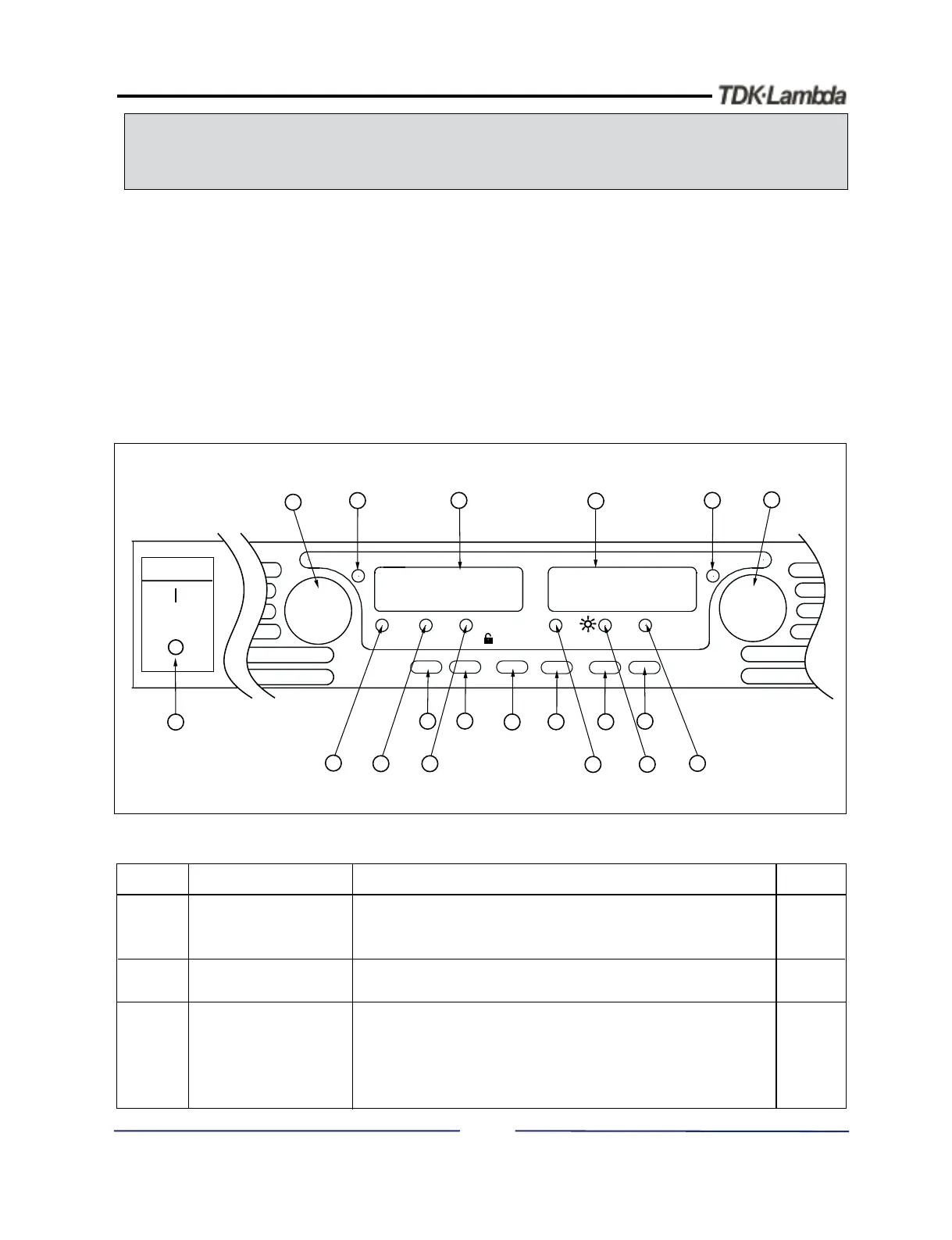
See Fig.4-1 to review the controls, indicators and meters located on the power supply front panel.
TM
Fig.4-1: Front panel controls and indicators
27
1
Number
Control/Indicator
Description
Section
High resolution rotary encoder for adjusting the Output
Voltage. Also adjusts the OVP/UVL levels and selects
theAddress.
VOLTAGE control
VOLTAGE indicator
Green LED , lights for Constant-Voltage mode
operation.
2
3
VOLTAGE display
4 digit, 7-segment LED display. Normally displays the
output voltage. When the PREV button is pressed, the
display indicates the programmed setting of the output
voltage. When the OVP/UVL button is pressed, the
Voltage display indicates the OVP/UVL setting.
Table 4-1: Front Panel controls and indicators
VOLTAGE
ALARM
FINE
PREV/
OVP
UVL
FOLD
REM/LOC
OUT
DC AMPS
CURRENT
'
'
'
'
'
'
'
'
DC VOLTS
POWER
1
14
17
18
19
2
15
16
3
13
10
4
11
5
12
9
6
7
8
5.2.1
5.3.1
5.4.1
7.2.2
Bekijk gratis de handleiding van TDK-Lambda GEN20-76, stel vragen en lees de antwoorden op veelvoorkomende problemen, of gebruik onze assistent om sneller informatie in de handleiding te vinden of uitleg te krijgen over specifieke functies.
Productinformatie
| Merk | TDK-Lambda |
| Model | GEN20-76 |
| Categorie | Niet gecategoriseerd |
| Taal | Nederlands |
| Grootte | 8526 MB |


