Supermicro X14SBT-GAP handleiding
Handleiding
Je bekijkt pagina 55 van 142
I²C Select for Backplane or Riser Card/AIOM
Use this jumper to select whether Backplane or Riser Card/AIOM should be used for the MCIO
connectors on the X14SBT-GAP motherboard. Use JI2C1 (JPCIE1A1) for JPCIE1A1, JI2C1
(JPCIE2A1) for JPCIE2A1, JI2C2 (JPCIE1B1) for JPCIE1B1 and JI2C2 (JPCIE2B1) for
JPCIE2B1.
I²C Select for Backplane or Riser Card/AIOM
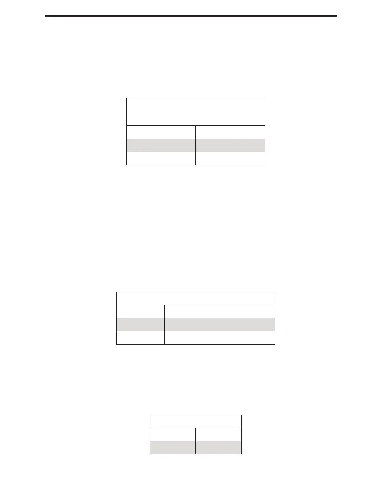
Jumper Settings
Jumper Setting Definition
Pins 1–2 Backplane (Default)
Pins 2–3 Riser Card or AIOM
LED Indicators
For information about the LED indicators on the X14SBT-GAP motherboard, refer to the
following content.
Onboard Power LED
The Onboard Power LED is located on the X14SBT-GAP motherboard. When this LED is on,
the system is on. Be sure to turn off the system and unplug the power cord before removing or
installing components.
For a detailed diagram of the X14SBT- GAP motherboard, see the layout under "Quick
Reference" on page 12.
Onboard Power LED Indicator
LED Color Definition
Off System Power Off (power cable not connected)
Green System Power On
P3V3_AUX Power LED
The P3V3_AUX Power LED at LED1 on the X14SBT-GAP motherboard monitors the status of
P3V3_AUX power.
For a detailed diagram of the X14SBT- GAP motherboard, see the layout under "Quick
Reference" on page 12.
P3V3_AUX Power LED State
LED Color Definition
Solid Yellow Power On
55
X14SBT-GAP: Component Installation
Bekijk gratis de handleiding van Supermicro X14SBT-GAP, stel vragen en lees de antwoorden op veelvoorkomende problemen, of gebruik onze assistent om sneller informatie in de handleiding te vinden of uitleg te krijgen over specifieke functies.
Productinformatie
| Merk | Supermicro |
| Model | X14SBT-GAP |
| Categorie | Niet gecategoriseerd |
| Taal | Nederlands |
| Grootte | 15560 MB |


