Supermicro X14SBHM handleiding
Handleiding
Je bekijkt pagina 14 van 152
Notes:
l
See "Component Installation" on page 23 for detailed information on jumpers,
connectors, and LED indicators.
l
"■" indicates the location of pin 1.
l
Components not documented are for internal testing only.
l
Use only the correct type of onboard CMOS battery as specified by the
manufacturer. Do not install the onboard battery upside down to avoid possible
explosion.
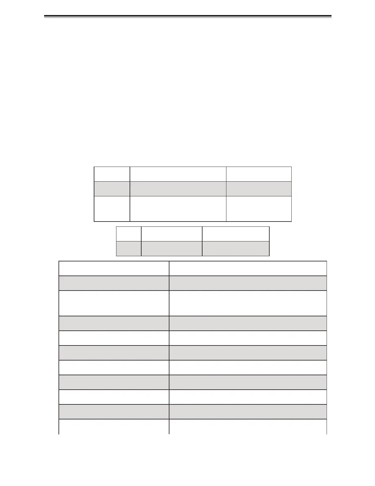
Quick Reference Table
Jumper Description Default Setting
JBT1 CMOS Clear Open (Normal)
JRU1 Front Control Board (JFP1) Signal
Pins 1–2 UID (Default)
Pins 2–3 Reset
LED Description Status
LE1 Onboard Power LED Solid Green: Power On
Connector Description
BT1 Onboard Battery
J1PE4, J1PE5, J1UP0, J1UP1, J1UP2,
J2PE4, J2PE5, J2UP0, J2UP1, J2UP2
MCIO PCIe 5.0 x8 Connectors
JAIOM1 Supermicro Advanced Input/Output Module PCIe 5.0 x16
JBOOT1 Reserved for M.2 Boot Tray (AOM-DCM2-BOOT)
JDCSCM Reserved for DC-SCM for AOM-SCM-DC6
JFP1 Front Control Board Header
JIPMB1 System Management Bus Header (for IPMI only)
JL1 Chassis Intrusion Header
JLXIO1 M-XIO PCIe 5.0 x16 Slot
JNCSI NC-SI Port Selection
14
X14SBHM: Introduction
Bekijk gratis de handleiding van Supermicro X14SBHM, stel vragen en lees de antwoorden op veelvoorkomende problemen, of gebruik onze assistent om sneller informatie in de handleiding te vinden of uitleg te krijgen over specifieke functies.
Productinformatie
| Merk | Supermicro |
| Model | X14SBHM |
| Categorie | Niet gecategoriseerd |
| Taal | Nederlands |
| Grootte | 19335 MB |


