Supermicro X11SSM handleiding
Handleiding
Je bekijkt pagina 44 van 124
44
X11SSM(-F)/X11SSL(-F) User Manual
Power Button
OH/Fan Fail LED
1
NIC1 Link Active LE
D
Reset Button
2
Power Fail LED
HDD LED
FP PWRLED
Reset
PWR
P3V3
P3V3_STBY/ID_UID_SW
UID LED
Ground
Ground
19 20
P3V3
NC
Ground
SW_NMI_N
NC
NIC2 Link Active LE
D
P3V3_STBY
P3V3_STBY
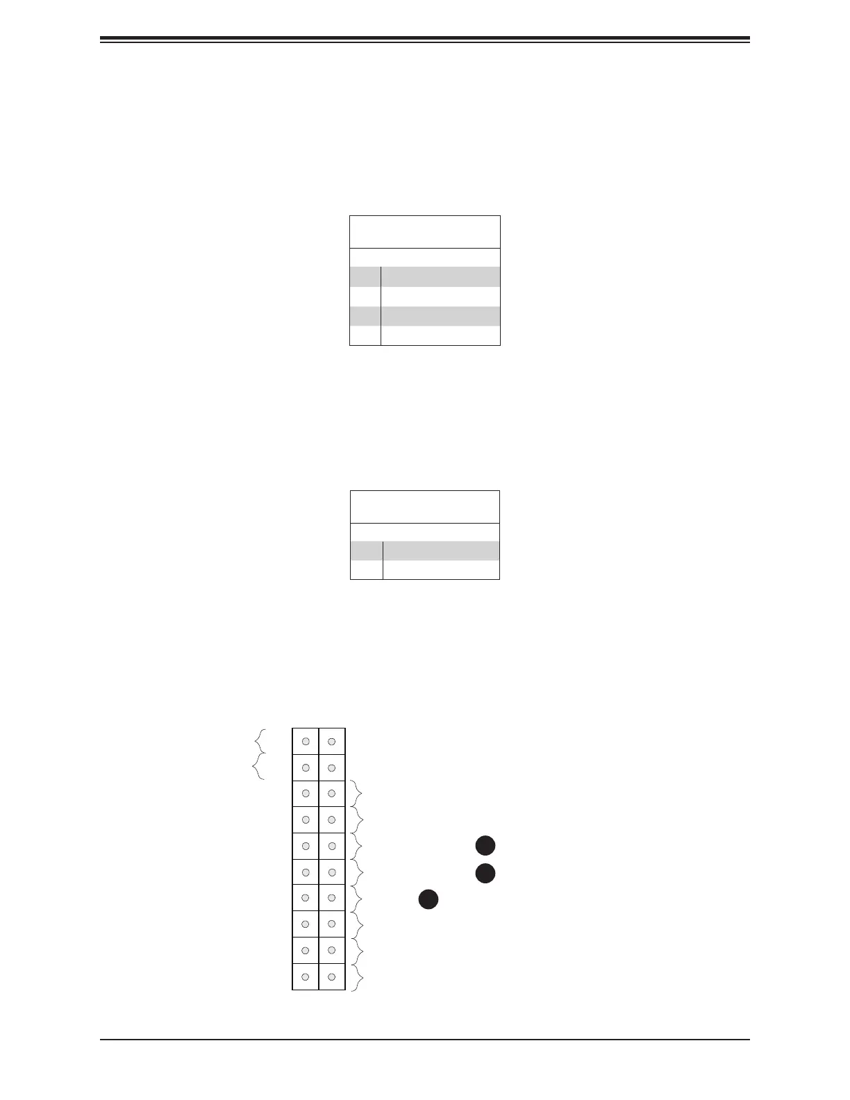
NIC1/NIC2 (LAN1/LAN2)
The NIC (Network Interface Controller) LED connection for LAN port 1 is located on pins 11
and 12 of JF1, and the LED connection for LAN port 2 is on pins 9 and 10. Attach the NIC
LED cables here to display network activity. Refer to the table below for pin denitions.
LAN1/LAN2 LED
Pin Denitions (JF1)
Pin# Denition
9 NIC 2 Activity LED
10 NIC 2 Link LED
11 NIC 1 Activity LED
12 NIC 1 Link LED
HDD LED/UID Switch
The HDD LED/UID Switch connection is located on pins 13 and 14 of JF1. Attach a cable to
pin 14 to show hard drive activity status. Attach a cable to Pin 13 to use UID switch. Refer
to the table below for pin denitions.
HDD LED
Pin Denitions (JF1)
Pin# Denition
13 3.3V Stdby/UID_SW
14 HDD Active
1. NIC2 LED
2. NIC1 LED
3. HDD LED / UID Switch
1
2
3
Bekijk gratis de handleiding van Supermicro X11SSM, stel vragen en lees de antwoorden op veelvoorkomende problemen, of gebruik onze assistent om sneller informatie in de handleiding te vinden of uitleg te krijgen over specifieke functies.
Productinformatie
| Merk | Supermicro |
| Model | X11SSM |
| Categorie | Niet gecategoriseerd |
| Taal | Nederlands |
| Grootte | 19665 MB |
Caratteristiche Prodotto
| Breedte | 244 mm |
| Diepte | 244 mm |
| Ethernet LAN | Ja |
| Aantal USB 2.0-poorten | 2 |
| VGA (D-Sub)poort(en) | 1 |


