Supermicro X11SSM handleiding
Handleiding
Je bekijkt pagina 41 van 124
41
Chapter 2: Installation
Power Button
OH/Fan Fail LED
1
NIC1 Link Active LE
D
Reset Button
2
Power Fail LED
HDD LED
FP PWRLED
Reset
PWR
P3V3
P3V3_STBY/ID_UID_SW
UID LED
Ground
Ground
19 20
P3V3
NC
Ground
SW_NMI_N
NC
NIC2 Link Active LE
D
P3V3_STBY
P3V3_STBY
CPU
VGA
LAN2
LAN1
LE1
COM1
COM2
USB6/7
(3.0)
USB0/1
IPMI_LAN
JOH1
JUIDB1
BAR CODE
IPMI CODE
MAC CODE
FAN4
JPWR2
JPWR1
JPL1
DIMMB2
DIMMB1
DIMMA2
DIMMA1
LED BMC
JPI2C1
JPL2
CPU SLOT7 PCI-E 3.0 x8
FAN1
FAN2
FAN3
FANA
LED PWR
JSTBY1
JWD1
I-SGPIO1 I-SGPIO2
USB10(3.0)
USB8/9(3.0)
JSD1
JF1
I-SATA0
I-SATA1
JSD2
I-SATA2
I-SATA3
I-SATA4
I-SATA5
I-SATA6
I-SATA7
USB4/5
JTPM1
JBT1
JL1
USB2/3
JD1
JPG1
JBR1
JPME2
JPB1
JI2C1
JI2C2
X11SSM(-F)/X11SSL(-F)
REV:1.01
Designed in the USA
BMC
MEGERAC
LICENSE
CPU SLOT6 PCI-E 3.0 x8(IN x16)
PCH SLOT5 PCI-E 3.0 x4(IN x8)
PCH SLOT4 PCI-E 3.0 x4(IN x8)
JIPMB1
SP1
Intel PCH
BT1
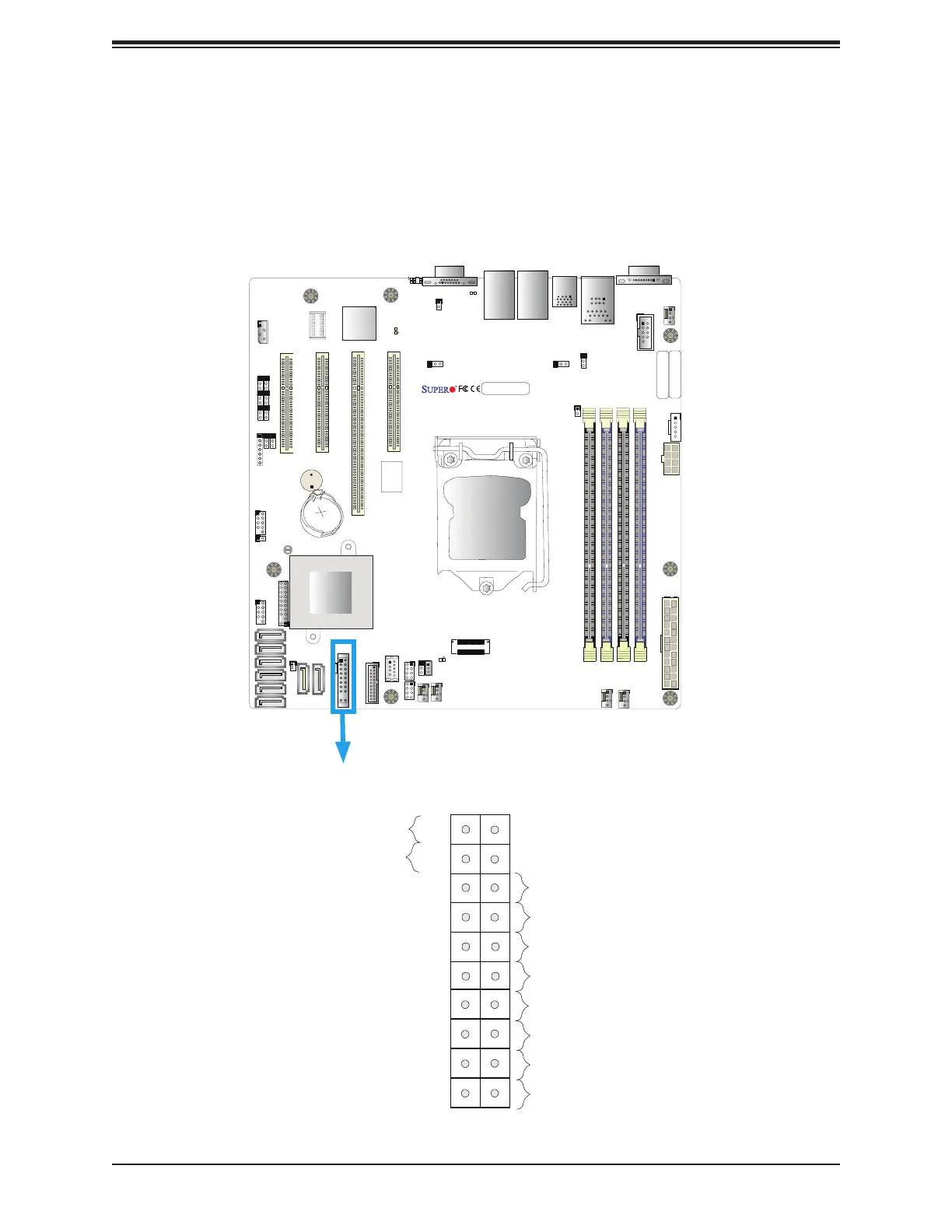
Figure 2-3. JF1 Header Pins
2.6 Front Control Panel
JF1 contains header pins for various buttons and indicators that are normally located on a
control panel at the front of the chassis. These connectors are designed specically for use
with Supermicro chassis. See the gure below for the descriptions of the front control panel
buttons and LED indicators.
Bekijk gratis de handleiding van Supermicro X11SSM, stel vragen en lees de antwoorden op veelvoorkomende problemen, of gebruik onze assistent om sneller informatie in de handleiding te vinden of uitleg te krijgen over specifieke functies.
Productinformatie
| Merk | Supermicro |
| Model | X11SSM |
| Categorie | Niet gecategoriseerd |
| Taal | Nederlands |
| Grootte | 19665 MB |
Caratteristiche Prodotto
| Breedte | 244 mm |
| Diepte | 244 mm |
| Ethernet LAN | Ja |
| Aantal USB 2.0-poorten | 2 |
| VGA (D-Sub)poort(en) | 1 |


