Supermicro CARAM5-M handleiding
Handleiding
Je bekijkt pagina 47 van 97
Onboard Battery (BT1)
The onboard backup battery is located at BT1. The onboard battery provides backup power to
the on-chip CMOS, which stores the BIOS' setup information. It also provides power to the Real
Time Clock (RTC) to keep it running.
PCIe M.2 Connectors (M.2-C1, M.2-P1)
The PCIe M.2 connectors are for devices such as memory cards, wireless adapters, etc. These
devices must conform to the PCIe M.2 specifications (formerly known as NGFF). These
particular PCIe M.2 connectors support M-Key (PCIe x4) storage cards. M.2-C1 supports a
speed of PCIe 5.0, while M.2 -P1 supports a speed of PCIe 4.0 only.
For a detailed diagram of the CARAM5- M motherboard, see the layout under "Quick
Reference" on page 11.
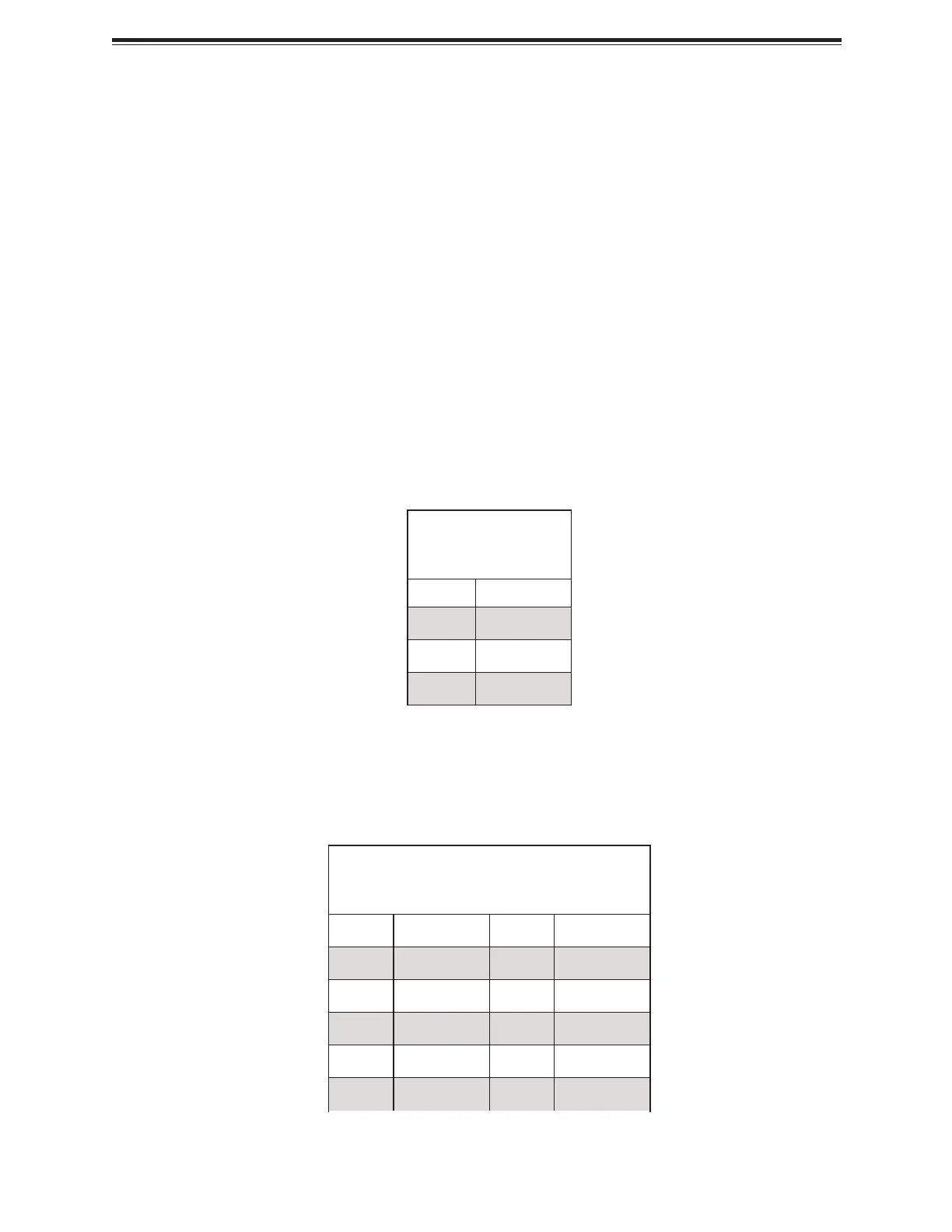
Standby Power Header
A Standby Power header is located at JSTBY1 on the CARAM5-M motherboard.
Standby Power
Pin Definitions
Pin# Definition
1 +5 V Standby
2 Ground
3 Wake-up
USB Ports (USB0~3, USB4~5, USB6~7, USB8~9, USB10~11)
There are a total of 12 USB ports supported on the CARAM5-M motherboard. Eight are located
on the rear panel, and four are located on the front panel. Note that USB devices are not able to
wake up from an S3/S4 state.
Rear Panel USB8~9 (3.2)
Pin Definitions
Pin# Definition Pin# Definition
1 +5 V
2 USB32_RN 19 +5 V
3 USB32_RP 18 USB32_RN
4 GND 17 USB32_RP
5 USB32_TN 16 GND
47
CARAM5-M: Component Installation
Bekijk gratis de handleiding van Supermicro CARAM5-M, stel vragen en lees de antwoorden op veelvoorkomende problemen, of gebruik onze assistent om sneller informatie in de handleiding te vinden of uitleg te krijgen over specifieke functies.
Productinformatie
| Merk | Supermicro |
| Model | CARAM5-M |
| Categorie | Niet gecategoriseerd |
| Taal | Nederlands |
| Grootte | 14422 MB |


