Supermicro Blade SBI-621E-1NE38 handleiding
Handleiding
Je bekijkt pagina 15 van 61
26 27
Chapter 2: Installation and Setup Chapter 2: Installation and Setup
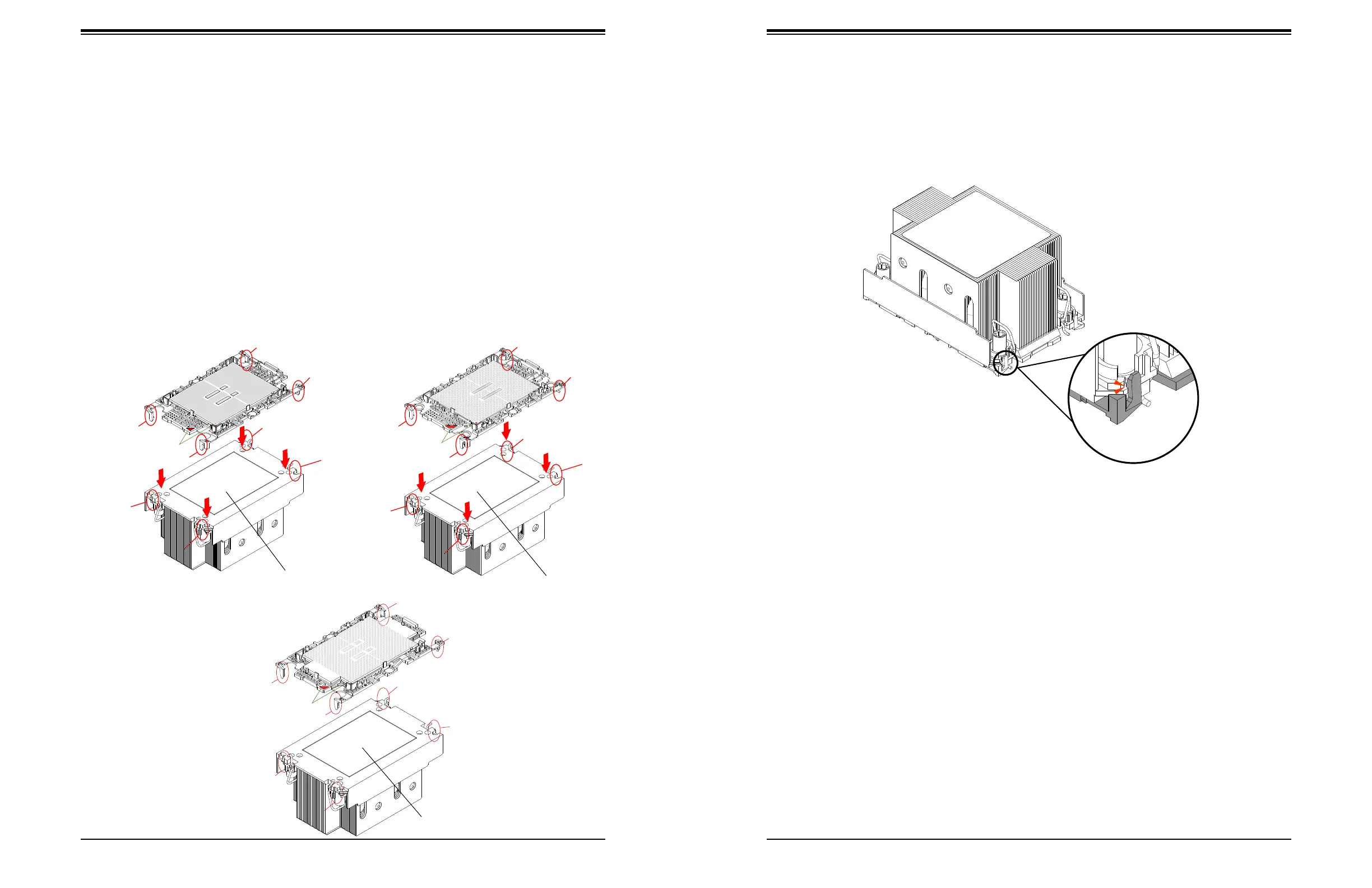
4. Align "a" on the processor carrier assembly with the triangular cutout "A" on the heatsink
along with "b", "c", "d" on the processor assembly with "B", "C", "D" on the heatsink.
5. Once properly aligned, place the heatsink on the processor carrier assembly with all
corners matched up, making sure that the four clips are properly securing the heatsink.
Note: The gure is for illustrative purposes. Your components may dier slightly from the
components shown.
Assembled PHM
Pin 1
a
c
b
d
A
C
D
B
Pin 1
a
c
b
d
A
C
D
B
Pin 1
a
c
b
d
A
C
D
B
Assemble the Processor Heatsink Module
Thermal grease is pre-applied on a new heatsink. No additional thermal grease is needed.
If this is a re-installation, apply the proper amount of thermal grease to the underside of the
heatsink.
Assembling the Processor Heatsink Module (PHM)
1. Turn the heatsink over with the thermal grease facing up. Locate the two triangle cutouts
(A, B) at the diagonal corners of the heatsink as shown in the drawing below.
2. Hold the processor carrier assembly component side up to locate the triangles on the
processor and the carrier, which indicate pin 1.
3. Turn the processor carrier assembly over so that the gold pins are facing up, noting the
two pin 1 locations ("A" on the processor and "a" on the processor carrier assembly).
Processor Carrier Assembly
(Component Side)
Heatsink (Bottom Side)
SP XCC
Heatsink (Bottom Side)
SP MCC/LCC
SP HBM
Heatsink (Bottom Side)
Bekijk gratis de handleiding van Supermicro Blade SBI-621E-1NE38, stel vragen en lees de antwoorden op veelvoorkomende problemen, of gebruik onze assistent om sneller informatie in de handleiding te vinden of uitleg te krijgen over specifieke functies.
Productinformatie
| Merk | Supermicro |
| Model | Blade SBI-621E-1NE38 |
| Categorie | Niet gecategoriseerd |
| Taal | Nederlands |
| Grootte | 19299 MB |


