Sony ZRD-VS25FM handleiding
Handleiding
Je bekijkt pagina 22 van 100
EN
22
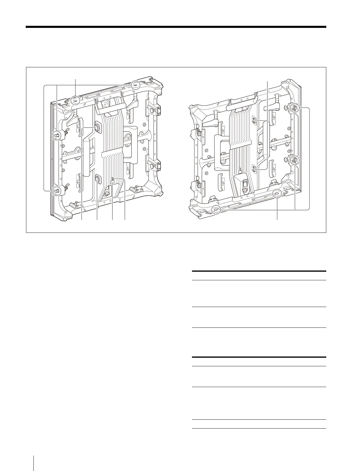
Parts Identification
Parts Identification
Left/Right
Cabinet joints
Connect to other Display Cabinets.
There are two cabinet joints on the right side,
l
eft
side, top and bottom.
P
WR OUT (AC power output) connector
Us
e a power cord for connecting between the
cab
inets*
1
(not supplied) to connect this
connector to the PWR IN (AC power input)
connector on the succeeding Display Cabinet in
the daisy-chain connection.
This connector is not used for the last Display
Cab
inet in
the daisy-chain connection.
PWR IN (AC power input) connector
Us
e a power cord for connecting between the
cab
inets*
1
(not supplied) to connect this
connector to the PWR OUT (AC power output)
connector on the preceding Display Cabinet in
the daisy-chain connection.
For the first Display Cabinet in the daisy-chain
c
onnectio
n, use a power cord for connecting
between the power and the cabinet*
2
(not
supplied) to connect this connector to the
circuit breaker.
TE
ST switch
By u
sing the switch, the test pattern can be
displaye
d without connecting the controller.
ST
ATUS indicator
Indi
cates the system status of the Display
Cabinet.
ɠɟɡɢ
ɞ
ɣ
ɞ
Operation Description
Press and hold Normal mode: Goes into test
patt
ern mode.
Test pattern mode: Goes into
norm
al mode.
Press Normal mode: No changes
Test pattern mode: Changes the
t
est pattern.
Status ZRD-VS25FB ZRD-VS25FM
The Display
Cabinet is turned
off
Off Off
The system is in the
start
up state*
3
Lit red Lit white
Lit magenta
Lit y
ellow
Returns to lit
white
Error status Blinking red Blinking red
Bekijk gratis de handleiding van Sony ZRD-VS25FM, stel vragen en lees de antwoorden op veelvoorkomende problemen, of gebruik onze assistent om sneller informatie in de handleiding te vinden of uitleg te krijgen over specifieke functies.
Productinformatie
| Merk | Sony |
| Model | ZRD-VS25FM |
| Categorie | Niet gecategoriseerd |
| Taal | Nederlands |
| Grootte | 14863 MB |


