Sony SNC-RH164 handleiding
Handleiding
Je bekijkt pagina 2 van 2
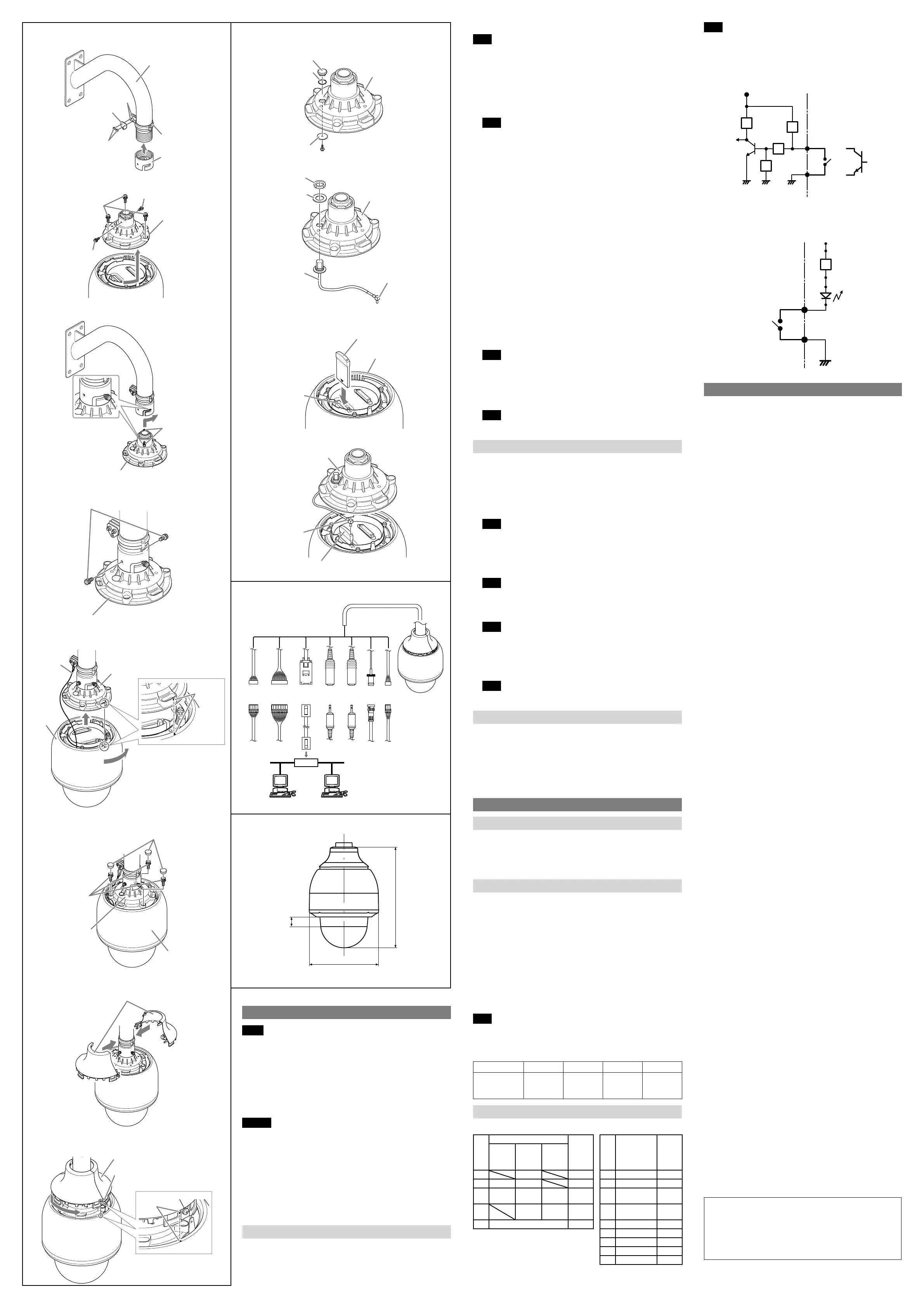
How to install the camera
Note
All bolts used for installation should be tightened to 5 N•m (torque wrench
setting).
1 Attach the supplied wire-fixing belt and wire bracket to the mounting arm
(not supplied). Then secure the wire-fixing belt and wire bracket to the
mounting arm by tightening two nuts.
The fall-prevention wire goes through the hole of the wire bracket. Tighten
the nuts securely to fix the wire bracket.
2 Screw the supplied coupling on the mounting arm.
Note
If the coupling is attached loosely or loosens, the camera may fall. Securely
put the coupling around the mounting arm so that it will not loosen.
3 Remove the three bolts from the top part of the camera, and turn the top
unit so the triangular mark aligns with the camera unit, then pull it upward to
remove it from the camera.
Have a 5 mm hex wrench ready to loosen the bolts.
4 Temporarily fix the two supplied bolts in the screw holes in the top part of the
top unit.
Insert the bolts about 3 mm into the screw holes.
5 Connect the cable from the mounting arm and the cable from the top unit.
Then push the connected cable into the mounting arm.
6 Attach the top unit to the mounting arm using the bolts.
Place the bolts temporarily fixed to the top unit in the groove of the coupling
and turn completely in the direction of the arrow. Then tighten the bolts
firmly.
7 Attach the two supplied bolts to the screw holes of the coupling and tighten
them.
8 Hook the fall-prevention wire of the camera on the hole of the wire bracket.
9 Align the respective triangular marks of the camera and top unit and push the
camera into the top unit. Then turn the camera completely in the direction of
the arrow.
10 Attach the camera to the top unit using the three bolts which were removed
in step 3.
11 Place the supplied waterproof covers on the tightened bolts.
12 Separate the provided top sunshade and reattach the separated parts above
the camera to return the top sunshade to its original form.
Note
Run the fall-prevention wire through the top sunshade.
13 Align the respective triangular marks of the camera and top sunshade and
push the top sunshade into the camera. Then turn the sunshade completely
in the direction of the arrow.
14 Secure the camera and top sunshade using the screw on the top sunshade.
Note
Please make sure to attach the top sunshade. The top sunshade prevents the
device from overheating in direct sunlight.
How to install the wireless LAN
The optional Wireless Card (SNCA-CFW5*), Wireless LAN Antenna (SNCA-AN1)
and Outdoor Antenna Cable Kit (SNCA-CW5) is required to use the wireless LAN.
* SNCA-CFW5 is not available in some countries and areas. For details, contact
your authorized Sony dealer.
1 Remove the top unit following Step 3 of “How to install the camera.”
2 Remove a screw on the top unit and remove the washer, hiding cover and the
O-ring.
Note
The removed parts are needed for removing the inner cable of the Antenna
Cable Kit. Keep the parts safe, as the loss of the part(s) will impair the
waterproofing characteristic.
3 Attach the inner cable of the Outdoor Antenna Cable Kit (SNCA-CW5) to the
top unit and tighten it with washer and nut supplied with the cable.
Note
Make sure to tighten the nut; if the nut loosens it will impair the
waterproofing characteristic.
4 Insert the Wireless Card into the card slot of the camera properly.
Note
Inserting the Wireless Card diagonally may damage the internal components.
The Wireless Card should be inserted perpendicularly.
5 Connect the MMCX connector of the Outdoor Antenna Cable Kit to the
connector of the Wireless Card. Then attach the camera to the top unit
following Step 10 of “How to install the camera.”
Note
Make sure the cable does not get caught between the camera and the top
unit.
Removing the camera
1 Remove the one screw that secures the top sunshade to the camera in Step
14 of “How to install the camera” to remove the top sunshade.
2 Remove the waterproof covers and three bolts fixed in Step 10 and 11 of
“How to install the camera.”
3 Turn the top unit to the position where the respective triangular marks of the
camera and top unit align, and pull the camera out downwards.
4 Remove the fall-prevention wire of the camera from the hole of the wire
bracket.
Connection
Connecting to the Network
Connect the LAN port of the camera unit to a router or hub in the network using
the network cable (straight, not supplied).
To connect to a computer
Connect the LAN port of the camera unit to the network connector of a
computer using the network cable (cross, not supplied).
Connecting the Power Source
Ensure safe and secure power supply preparation.
The minijacks and plug are non-lock connectors. After completely inserting
the connector, secure them with plastic tape and the like to prevent the
connectors from disconnected.
Other connectors are lock type. Make sure you insert them completely.
The BNC connector is a rotational lock type.
Connect the cable of the 24 V AC power supply system to the
power input terminal (pin 1 and pin 3 ) of the camera.
Take measures to ensure 24 V AC under a maximum current of 4 A.
– In the USA, The product shall be powered by a UL Listed Class 2 Power
Supply Only.
– In Canada, The product shall be powered by a CSA Certified Class 2 Power
Supply Only.
Use the UL cable (VW-1 style 10368) for 24 V AC connection.
Note
Always connect pin 2 (center) to the ground terminal.
Recommended power cable
Power supply at 24 V AC
Size: AWG
AWG22 AWG20 AWG18 AWG16
Maximum
length
(m (feet))
5 (16.4) 8 (26.2) 15 (49.2) 21 (68.9)
Pin alignment of I/O cable (supplied)
Serial communicable In/Out (5 pin) Alarm In/Out (9 pin)
Pin
No.
Pin name
Color
Pin
No.
Pin name Color
RS232C
RS422/
RS485
(Full)
RS485
(Half)
1 Rx− Yellow 1 Alarm out 2− Purple
2 Rx Rx+ Orange 2 Alarm out 2+ Purple
3 Tx Tx−
Tx−/
Rx−
Red 3 Alarm out 1− Blue
4 Tx+
Tx+/
Rx+
Brown 4 Alarm out 1+ Blue
5 GND Black 5 Sensor in 4 Yellow
6 Sensor in 3 Orange
7 Sensor in 2 Red
8 Sensor in 1 Brown
9 GND Black
Note
For details about functions and settings, see the user’s guide in the supplied
CD-ROM.
Wiring diagram for sensor input
Mechanical switch/open collector output device
10 kohms
Camera inside
3.3 V
10 kohms
GND
Mechanical
switch
Open collector
output device
Outside
or
2.2 kohms
10 kohms
GNDGND
Wiring diagram for alarm output
Camera inside
Alarm Output +
Magnet relay
24 V AC
24 V DC
1 A or less
Alarm Output –
Outside
24 V DC
Circuit example
R
GND
Specifications
Network
Protocol TCP/IP, ARP, ICMP, HTTP, FTP (server/client), SMTP
(client), DHCP (client), DNS (client), NTP (client),
SNMP (MIB-2), RTP/RTCP
Compression
Video compression format JPEG/MPEG4/H.264
Audio compression format G.711/G.726 (40,32,24,16 kbps)
Maximum frame rate SNC-RH164: JPEG/MPEG4/H.264: 30 fps
(1280 × 720)
SNC-RS86N/RS86P/RS84N/RS84P: JPEG/MPEG4/
H.264: 30 fps (720 × 480)
Camera
Camera system SNC-RH164: Camera HD (720P)
SNC-RS86N/RS86P/RS84N/RS84P: Camera SD
Signal system SNC-RH164:
NTSC colour/PAL colour switching system
SNC-RS86N/RS84N: NTSC colour system
SNC-RS86P/RS84P: PAL colour system
Image device SNC-RH164: 1/3 type CMOS
SNC-RS86N/RS86P/RS84N/RS84P:
1/4 type interline transfer CCD
Effective picture elements
SNC-RH164: Approx. 2 million
SNC-RS86N/RS84N: Approx. 380,000 (NTSC)
SNC-RS86P/RS84P: Approx. 440,000 (PAL)
Synchronisation system SNC-RH164: Internal synchronisation system
SNC-RS86N/RS86P/RS84N/RS84P:
Internal/Power synchronisation switching
Minimum illumination SNC-RH164: 2.1 lx (F1.8/AGC ON/50 IRE (IP))
SNC-RS86N/RS86P: 0.75 lx (F1.6/AGC ON/
50 IRE (IP))
SNC-RS84N/RS84P: 0.44 lx (F1.4/AGC ON/
50 IRE (IP))
Horizontal resolution SNC-RH164: 480 TV (analogue video output)
SNC-RS86N/RS86P/RS84N/RS84P:
530 TV (analogue video output)
Video S/N (AGC 0 dB) 50 dB or more
Lens
Focus distance SNC-RH164: 5.1 mm to 51 mm
SNC-RS86N/RS86P: 3.4 mm to 122.4 mm
SNC-RS84N/RS84P: 4.1 mm to 73.8 mm
Maximum SNC-RH164: F1.8 (wide), F2.1 (tele)
SNC-RS86N/RS86P: F1.6 (wide), F4.5 (tele)
SNC-RS84N/RS84P: F1.4 (wide), F3.0 (tele)
Minimum object distance SNC-RH164: 10 mm (wide) to 800 mm (tele)
SNC-RS86N/RS86P: 320 mm (wide) to 1500 mm
(tele)
SNC-RS84N/RS84P: 290 mm (wide) to 800 mm
(tele)
Mechanism
Pan 360°, endless rotation
Maximum speed: 400°/s
Tilt 210° (with auto invert function)
Maximum speed: 400°/s
Interface
Network port 10BASE-T/100BASE-TX, auto negotiation (RJ-45)
I/O port Sensor input: × 4, make contact
Alarm output: × 2, 24 V AC/DC, 1 A
(mechanical relay outputs electrically isolated
from the camera)
Video output VIDEO OUT: BNC, 1.0 Vp-p,
75 ohms, unbalanced, sync negative
CF card slot CF Type I/II
Microphone input Minijack (monaural)
Plug-in-power supported (rated voltage: 2.5 V
DC)
Recommended load impedance 2.2 khoms
* A selector menu allows switching between
microphone input and line input
Line input Minijack (monaural)
Recommended load impedance 10 kohms
* A selector menu allows switching between
microphone input and line input
Line output Minijack (monaural), Maximum output level:
1 Vrms
Others
Power supply 24 V AC ± 10%, 50 Hz/60 Hz
Power consumption SNC-RH164: Max. 80 W
SNC-RS86N/RS86P/RS84N/RS84P: Max. 78 W
Operating temperature –40°C to +50°C (–40°F to +122°F)
Storage temperature –20°C to +60°C (–4°F to +140°F)
Operating humidity 10% to 90% (Ensure no condensation)
Storage humidity 10% to 90%
Dimensions (Diameter/Height)
ø238 mm × 344 mm (ø9
3
/
8
inches × 13
5
/
8
inches)
(without the projecting parts)
Mass Approx. 4.3 kg (9 lb 8 oz)
Supplied accessories Top sunshade (1)
Coupling (1)
Wire fixing belt (1)
Bolts (4)
Connection harness 5-pin (1)
Connection harness 9-pin (1)
Installation manual (1 set)
CD-ROM (User’s Guide, supplied programs) (1)
Waterproof covers (3)
Optional accessories
Wireless Card SNCA-CFW5*
Wireless LAN Antenna SNCA-AN1
Outdoor Antenna Cable Kit SNCA-CW5
* SNCA-CFW5, SNCA-AN1 and SNCA-CW5 are not available in some countries and
areas. For details, contact your authorized Sony dealer.
Design and specifications are subject to change without notice.
Recommendation of Periodic Inspections
In case using this device over an extended period of time, please have it
inspected periodically for safe use.
It may appear flawless, but the components may have deteriorated over
time, which may cause a malfunction or accident.
For details, please consult the store of purchase or an authorized Sony
dealer.
3, 4
6
7
8, 9
10, 11
12
How to install the camera
Mounting arm
(not supplied)
Nuts
Wire-fixing belt
Coupling
Screws
Wire bracket
Top sunshades
13, 14
1, 2
Installation
Notes
Do not allow water to come in contact with the power cable, connection
cables or connectors, as it may cause water leakage into this device, and
subsequent damage.
The mounting arm (not supplied) to which the device is attached should have
fixing screws of NPT 11/2”.
When you install the camera, make sure you do not damage or spoil the dome
cover.
Ensure that the device is level, with the dome cover facing down.
The lens zoom and angle may result in a blurred or inclined image within the
range above the line of the dome cover ( a).
Warning
If installing the camera in high location, such as high wall, entrust the
installation to a professional contractor or service personnel.
The camera should be securely installed on a location strong enough to
support the weight of the camera and the mounting arm. Otherwise, the
camera and mounting arm may fall and cause serious injury.
For the fall-prevention of the camera, make sure to use the wire rope.
If the bolts are attached loosely or loosen, the camera and parts may fall. There
may also be a risk of water leakage. Make sure to tighten the bolts and screws
so that they will not loosen.
Check the camera is attached securely, the screws, etc. are not loosened
periodically, at the least once a year. Depending on the usage conditions,
periodic inspections should be conducted more frequently.
How to Install
Before installation
Referring to the installation manual of the mounting arm (not supplied), drill the
required holes for the mounting screws and the connection cable. Then install
the mount arm in advance.
Bolt
Top unit
Bolts (3)
Bolt
Bolts (2)
Top unit
Bolts (2)
Top unit
Fall-prevention
wire
Camera
Top unit
Align the
triangular
marks
Waterproof covers (3)
Bolts (3)
Top unit
Camera
Top sunshade
Screw
Align the
triangular marks
How to install the wireless LAN
2
3
4
5
Hiding cover
O-ring
Top unit
Washer
Nut
Washer
Top unit
Inner cable of
the Antenna
Cable Kit
(optional)
MMCX connector
Card slot
Wireless Card (optional)
Camera
Top unit
MMCX
connector
Wireless Card
5-pin
Connector
LAN
Audio
Output
Mic
Input
Video
Output
To 24 V
AC
9-pin
Connector
Unit: mm (inches)
344 (13
5
/
8
)
ø238 (9
3
/
8
)
a
Bekijk gratis de handleiding van Sony SNC-RH164, stel vragen en lees de antwoorden op veelvoorkomende problemen, of gebruik onze assistent om sneller informatie in de handleiding te vinden of uitleg te krijgen over specifieke functies.
Productinformatie
| Merk | Sony |
| Model | SNC-RH164 |
| Categorie | Bewakingscamera |
| Taal | Nederlands |
| Grootte | 1203 MB |
Caratteristiche Prodotto
| Gewicht | 4300 g |
| Stroomvoorziening | AC 24V |
| Ondersteunde videoformaten | H.264 |
| Maximum resolutie | 1280 x 720 Pixels |
| Minimale belichting | 2.1 Lux |


