Sony HDC-4300 handleiding
Handleiding
Je bekijkt pagina 11 van 71
11
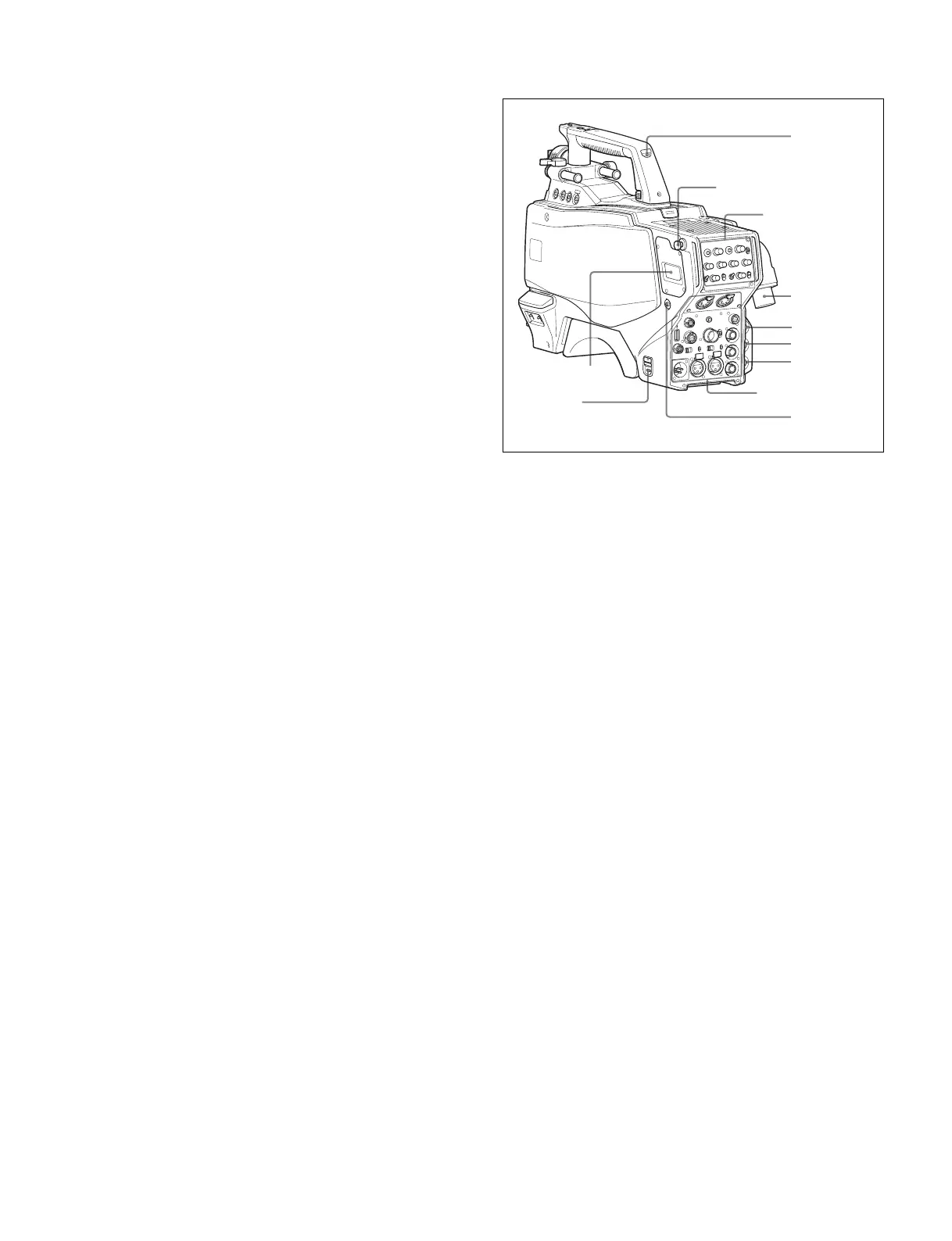
b RET 1 (return video 1) button
The return video 1 signal from the camera control unit is
monitored on the viewfinder screen while this button is
pressed. It functions the same as the RET 1 buttons on the
handle (page 10) and on the operation panel on the rear of the
camera (page 12 (JN/SY models) or page 13 (CE/CN
models)).
You can also assign other functions to this button, using the
menu displayed on the viewfinder screen.
c MIC 1 IN (microphone 1 input) connector (XLR 3-pin)
Connect a microphone.
This connector and the AUDIO IN CH1 connector (page 14)
on the connector panel on the rear of the camera are
alternately activated with the CH1 audio input select switch
(page 14).
d MIC (microphone) power switch
+48V: To supply power at +48 V to the microphone connected
to the MIC 1 IN connector.
OFF: Not to supply power to the microphone connected to the
MIC 1 IN connector.
e SHUTTER switch
For setting the electronic shutter functions when the camera is
used in standalone status without connecting a camera control
unit.
OFF: The electronic shutter does not function.
ON: The electronic shutter is activated.
SEL: The shutter speed and shutter mode change each time
the switch is set to this position.
For details, see “Setting the Electronic Shutter” on page 22.
f INTERCOM LEVEL control
To adjust the intercom/earphone volume level.
The intercom level adjustment is enabled when the
INTERCOM 1 and 2 LEVEL/MIC switches (on the JN/SY-
model operation panel (page 12)) or the LEVEL switch (on the
CE/CN-model operation panel (page 13)) on the rear of the
camera are set to FRONT.
g RET 2 (return video 2) button
When this button is pressed, the picture on the viewfinder
screen changes to the return video signal selected with the
RET 2 select switch (page 12 (JN/SY models) or page 13 (CE/
CN models)) on the operation panel on the rear of the camera.
You can also assign other functions to this button, using the
menu displayed on the viewfinder screen.
Rear
a DC power supply out connector (2-pin)
Supplies power to an external device up to 2.5 A.
b CAMERA POWER switch
CCU: Power is supplied from the camera control unit.
EXT: Power is supplied through the DC IN connector.
c Tally lamp and switch
ON: The tally lamp lights when a tally signal is input to the
connected camera control unit or a call signal is
generated in response to pressing the CALL button.
OFF: The tally lamp is prevented from lighting.
d BPU (Baseband Processor Unit) connector (optical/
electrical multi-connector)
Connect to HDCU4300 Camera Control Unit or BPU4000/
4500 Baseband Processor Unit using an optical/electrical
multi cable.
e SDI 1 (serial digital interface 1) connector (BNC-type)
For 3G-SDI, HD-SDI or HD PROMPTER signal output.
f SDI 2 (serial digital interface 2) connector (BNC-type)
For HD-SDI signal output.
During standalone operation, also used for inputting an
HD-SDI return signal.
When RET (return) is set to 1, this is displayed in the
viewfinder.
g PROMPTER2 connector (BNC-type)
For prompter 2 signal output.
Available only when connecting a camera control unit with a
prompter 2 input connector.
During standalone operation, also used for inputting a VBS
return signal.
When RET (return) is set to 2, this is displayed in the
viewfinder.
h CALL button
When this button is pressed, the red tally lamp of the RCP-
1000 series Remote Control Panel or the MSU-1000 series
b
c
Shoulder strap fitting
post (page 9)
Operation panel
(page 12)
d
a
f
e
g
h
Connector panel
(page 13)
Bekijk gratis de handleiding van Sony HDC-4300, stel vragen en lees de antwoorden op veelvoorkomende problemen, of gebruik onze assistent om sneller informatie in de handleiding te vinden of uitleg te krijgen over specifieke functies.
Productinformatie
| Merk | Sony |
| Model | HDC-4300 |
| Categorie | Niet gecategoriseerd |
| Taal | Nederlands |
| Grootte | 8647 MB |


