Sony CNU-700 handleiding
Handleiding
Je bekijkt pagina 16 van 20
16
CAMERA COMMAND NETWORK UNIT
POWER
I
O
CHARACTER
REFERENCE
RS232C
CCU RCP
CCU RCP
123456123456MSU VCS AUX1 AUX2
789101112 7 8 9 1011 12 MSU VCS AUX3 AUX4
1
1
2
2
3
AC IN
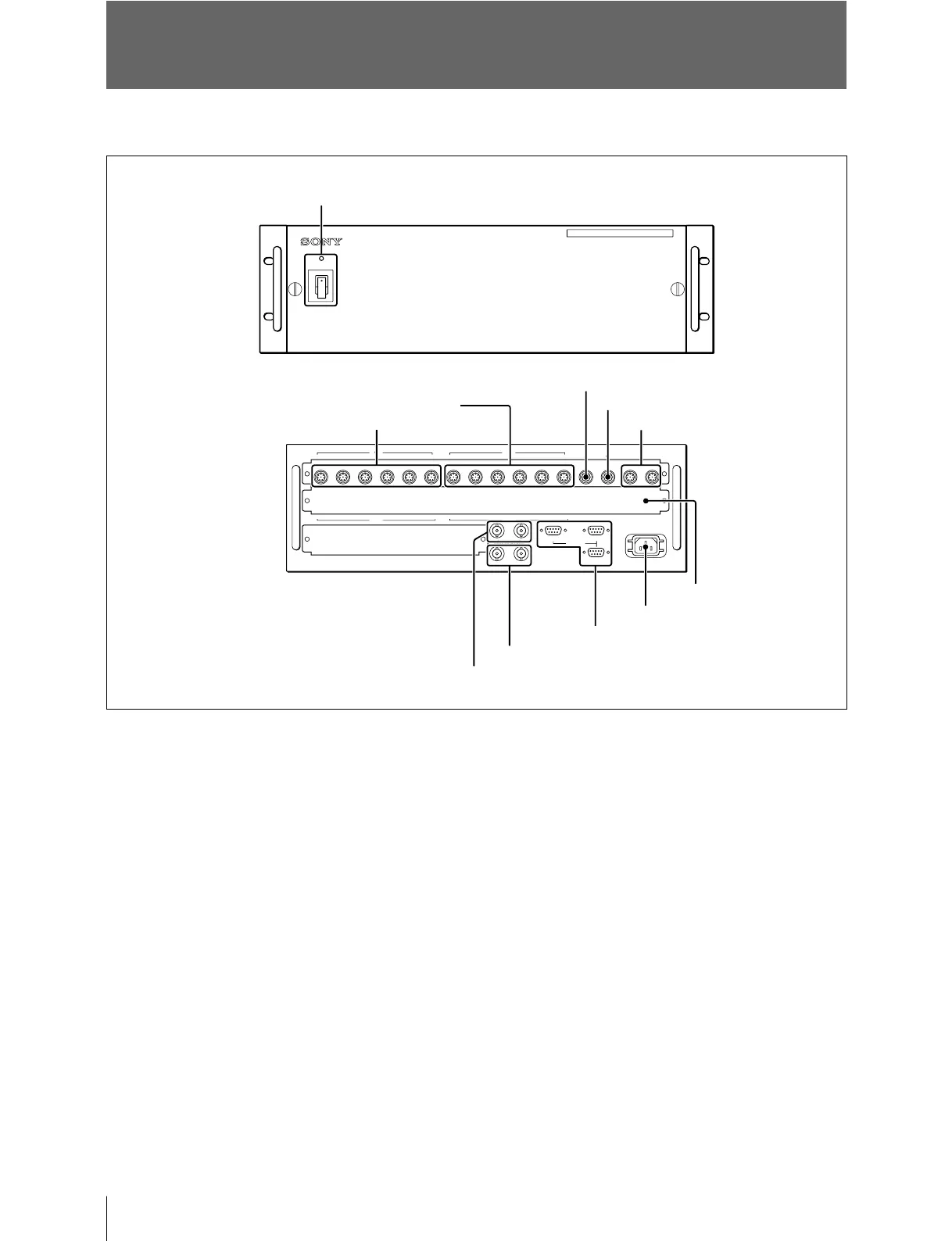
Location and Function of Parts and Controls
Rear panel
Front panel
1POWER switch and indicator
Press to turn the power ON or OFF. The indicator
lights when power is supplied.
2CCU (camera control unit) 1 through 6
connectors (8-pin)
Connect to the RCP/CNU REMOTE connector on
a CCU/HDCU-series Camera Control Unit using a
CCA-5 cable.
3RCP (remote control panel) 1 through 6
connectors (8-pin)
Connect to the CCU/CNU REMOTE connectors
on an RCP-series Remote Control Panel using a
CCA-5 cable.
4MSU (master setup unit) connector (8-pin)
Connect to the CCU/CNU REMOTE connector on
an MSU-900/1000 Master Setup Unit using a
CCA-5 cable.
5VCS (video selector) connector (8-pin)
Connect to the REMOTE connector of a VCS-700
Video Selector using a CCA-5 cable.
6AUX1 and AUX2 (auxiliary 1 and 2)
connectors (8-pin)
Connect to the AUX1 or AUX2 connector of
another CNU-700 using a CCA-5 cable when
controlling multiple cameras with two CNU-700s.
5VCS connector
7CHARACTER 1 and 2 connectors
8REFERENCE connectors
9RS232C 1 through 3 connectors
qaOptional board insertion
section
0-AC IN connector
6AUX1 and AUX2 connectors
1POWER switch and indicator
4MSU connector
3RCP 1 through 6 connectors
2CCU 1 through 6 connectors
Location and Function of Parts and Controls
Bekijk gratis de handleiding van Sony CNU-700, stel vragen en lees de antwoorden op veelvoorkomende problemen, of gebruik onze assistent om sneller informatie in de handleiding te vinden of uitleg te krijgen over specifieke functies.
Productinformatie
| Merk | Sony |
| Model | CNU-700 |
| Categorie | Niet gecategoriseerd |
| Taal | Nederlands |
| Grootte | 2981 MB |


