Sonifex DHY-04 handleiding
Handleiding
Je bekijkt pagina 16 van 56
2 Configuration & Controls - DHY-04, DHY-04S, DHY-04T
6
Rear Panel Controls & Connections
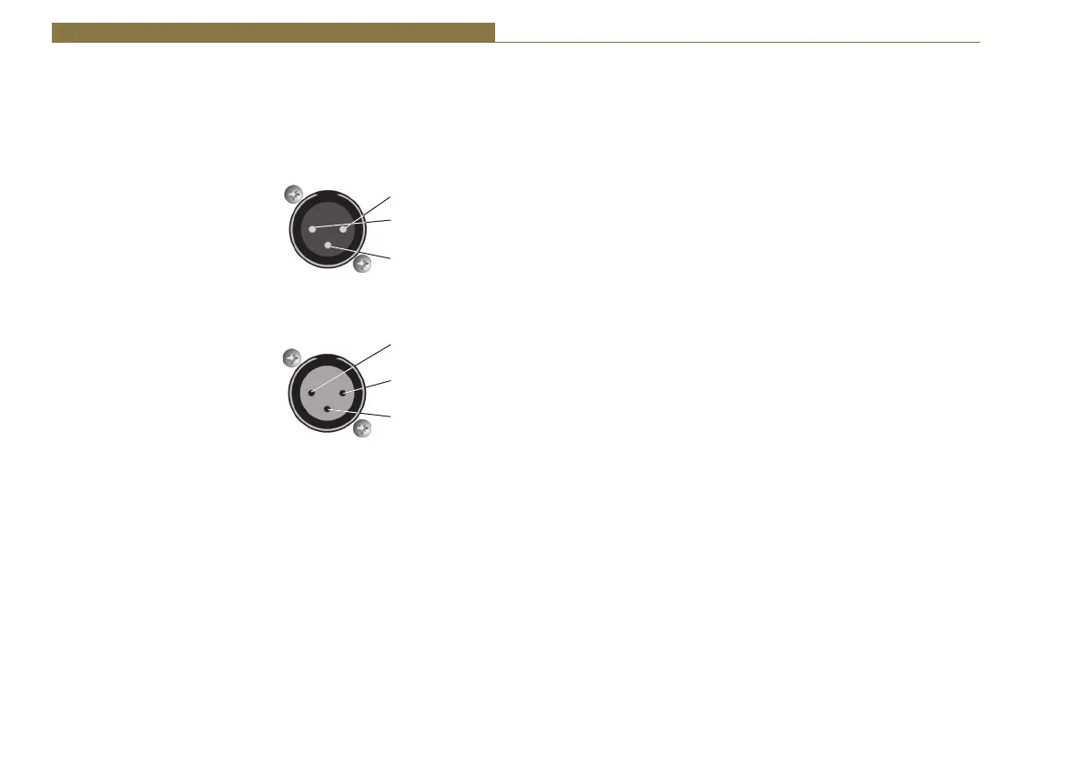
AES/EBU & Analogue Combined Line Output
The line output is an XLR 3 pin male connector with the following
connections (XLR-3-32, 50Ω balanced floating). It outputs either balanced
analogue or AES/EBU audio by following the input, i.e. a digital input
produces a digital output.
Pin 1: Screen
Pin 2: Phase
Pin 3: Non-Phase
Mic/Line & AES/EBU Input
The line input is an XLR 3 pin female connector (XLR-3-31, 10kΩ balanced
floating). It is autosensing for either analogue balanced or AES/EBU (left
channel) signals.
Pin 1: Screen
Pin 2: Phase
Pin 3: Non-Phase
Mic/Line Input Select Switch
This push-button switch sets the input signal mode:
Switch depressed (in) - Mic input mode selected
Switch not depressed (out) - Line input mode selected
Adjusting the Microphone Gain Level
The Mic Level preset potentiometer controls the level of the input signal
when the Mic/Line Input Select Switch is set to Mic input. The input signal
level in Line mode is factory set and is not affected by this control. The Mic
Input will accept 200Ω microphone level signals and is balanced/floating
with a maximum gain of 70dB. Use a jeweller’s screwdriver to adjust the
gain between 70dB and 52dB. The gain range can be extended by ±6dB by
using the front panel ‘Level to The Line’ switch.
Remotes
The remote port allows you to control the line hold circuit from a mixing
desk or other remote device and also outputs opto-isolated outputs to
indicate the line hold status and the DTMF detect function.
The remote connector is a 9-way female (socket) ‘D’ type. To remotely
control the line connect, connect pin 1 to pin 2. The action of this remote
can act as momentary or latching by pin 6 having no connection or
connecting to 0V respectively.
Pins 3 & 7 is an opto-isolated remote line connect indicator and pins 5 & 7
is an opto-isolated DTMF detect output. They can use the local supply pins
4 & 8 to drive an LED indicator or a low current load.
Pin 1: Remote Line Connect Switch
Pin 2: Common – 0V
Pin 3: Opto-Isolated Line Connect Indicator - NPN Emitter
Pin 4: Common – 0V
Pin 5: Opto-Isolated User GPO (DTMF Detect*) Indicator - NPN Emitter
Pin 6: User GPI (Momentary/Latch Line Connect Switch - connect to
0V for latching action*)
Pin 7: Opto-Isolated Line Connect Indicator - NPN Collector
Pin 8: 5V out (current limited supply for pins 7 & 9)
Pin 9: Opto-Isolated User GPO Indicator - NPN Collector
The remote line connect indicator mimics the front panel Line Hold/
Connect Switch lamp, i.e. it flashes when ringing and is on when the line is
held.
User GPO and GPI have their default functions (*) set to the same use as
the DHY-03.
Conference Audio/Record Output
This is an RJ45 analogue audio connector to cross connect to another
DHY-04. This will allow a single TBU channel on a mixing desk to handle 2
calls, one to each DHY-04. Alternatively the conference output signals can
Pin2
Phase Signal
Pin 1
Screen Signal
Pin 3
Non-Phase Signal
Pin2
Phase Signal
Pin 1
Screen Signal
Pin 3
Non-Phase Signal
Bekijk gratis de handleiding van Sonifex DHY-04, stel vragen en lees de antwoorden op veelvoorkomende problemen, of gebruik onze assistent om sneller informatie in de handleiding te vinden of uitleg te krijgen over specifieke functies.
Productinformatie
| Merk | Sonifex |
| Model | DHY-04 |
| Categorie | Niet gecategoriseerd |
| Taal | Nederlands |
| Grootte | 11611 MB |


