Sommer ASB-6010A handleiding
Handleiding
Je bekijkt pagina 60 van 61
60
1
4
5
8 9 10 11 13 14 15 16 17 18 19 20
2
3
6 7
LN
SAFETY
ALARMSTART1 START2
INDUC.1INDUC.2 CLOCK
24V
GND
SIGNAL
COM
WARNING
MOTOR
M
Limit
open
Limit
close
GND
PE
PE
LN
24VAC
24V
GND
12V
GND
MUFU 1
MUFU 2
12
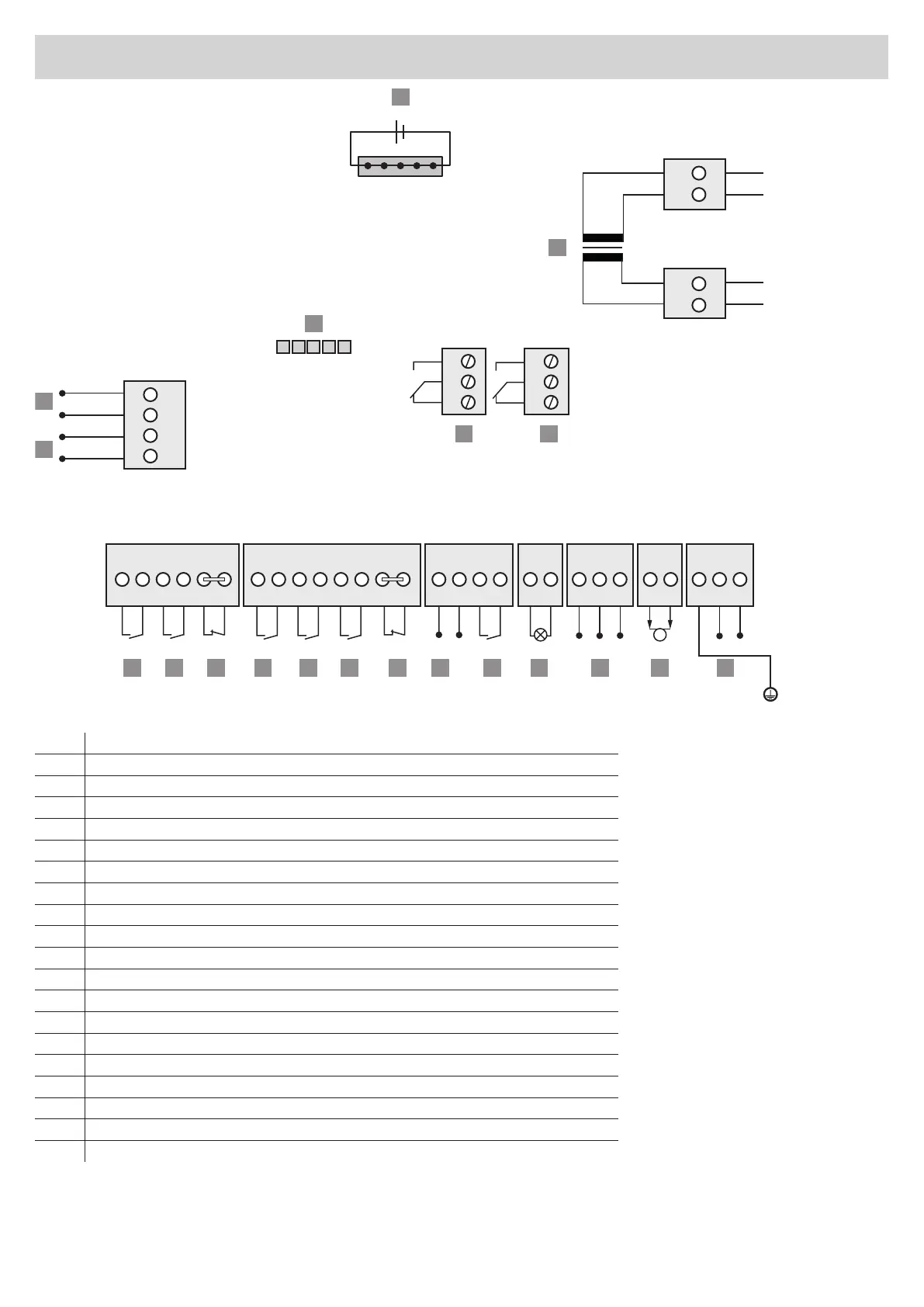
1) Transformer
2) Slot for Accu
3) Slot for Memo
4) Output 24 V DC max. 300 mA (600 mA*)
5) Output 12 V DC max. 150 mA
6) Multi-function relay slot
7) Multi-function relay slot
8) External button 1, potential-free
9) External button 2, potential-free
10) Emergency stop / targeted STOP, potential-free
11) NC contact, induction loop detector, potential-free
12) NO contact, induction loop detector, potential-free
13) Timer, potential-free
14) Alarm safety input, potential-free
15) Voltage supply 4-wire photocell 24 V DC, max. 100 mA
16) 2-wire photocell, switching contact 4-wire photocell, 8k2 safety contact strip
17) Warning light 24 V max. 3W
18) Limit stop OPEN / CLOSE
19) Motor
20) Mains connection 220-240 V AC 50/60 Hz
For colours of the lines on motor and limit stop connection, see "Connection options" on page 35
*600 mA are only available if no further external 24 V and 12 V device is connected to the control unit.
Connection diagram
Bekijk gratis de handleiding van Sommer ASB-6010A, stel vragen en lees de antwoorden op veelvoorkomende problemen, of gebruik onze assistent om sneller informatie in de handleiding te vinden of uitleg te krijgen over specifieke functies.
Productinformatie
| Merk | Sommer |
| Model | ASB-6010A |
| Categorie | Niet gecategoriseerd |
| Taal | Nederlands |
| Grootte | 7965 MB |


