SolaX Power T-Bat H 23 handleiding
Handleiding
Je bekijkt pagina 15 van 22
24
25
4. Installation
4. Installation
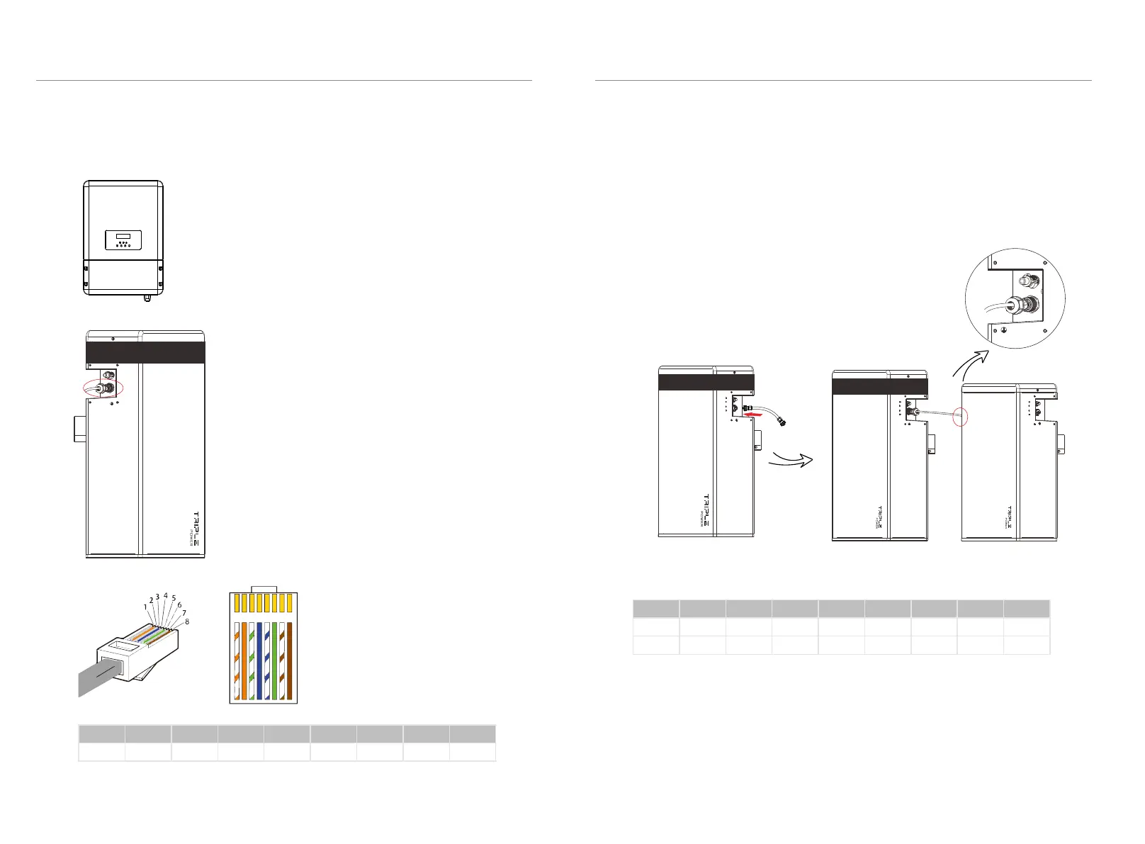
4.5.3 Connecting CAN Communication Cable
It is required for the BMS to communicate with the inverter for proper operation.
2. Insert the other end of the CAN communication
cable to the CAN connector (Ⅱ) on the first battery
which is marked in red.
Assemble the cable gland and tighten the cable
cap.
1. Insert one end of the CAN communication
cable (C) directly to the BMS port of the Inverter.
BAT- BAT+
CAN
The wiring order of the communication cable is as follow:
1 2
3
4
5
6 7 8
1) White with an orange stripe
2) Orange
3) White with a green stripe
4) Blue
5) White with a blue stripe
6) Green
7) White with a brown stripe
8) Brown
Sequence
1 2 3 4 5 6 7 8
CAN
/
GND
/
CAN_H
CAN_L
/
A1
B1
4.5.4 Connecting RS485 Communication Cable
For T-BAT H 5.8:
There's no need to use RS485 communicaton cable.
For T-BAT H 5.8 + 1~3 battery packs:
Connect RS485 II (Ⅶ for T-BAT H 5.8 or Ⅷ' for HV11550) of the first battery pack (as
shown on the right) to RS485 I on the next battery pack(as shown on the left).
Assemble the cable gland and tighten the cable cap.
Sequence 1 2 3 4 5
6
7 8
RS485I
RS485II
VCC_485
VCC_485
GND_485
GND_485
B2
B2
N-
N-
P+
P+
A2
A2
VCC_485_2
VCC_485_2
GND_485
GND_485
The wiring order of the communication cable is as follow:
-
YPLUG
RS485 II
-
YPLUG
RS485 II
-
YPLUG
RS485 II
+
XPLUG
RS485 I
Bekijk gratis de handleiding van SolaX Power T-Bat H 23, stel vragen en lees de antwoorden op veelvoorkomende problemen, of gebruik onze assistent om sneller informatie in de handleiding te vinden of uitleg te krijgen over specifieke functies.
Productinformatie
| Merk | SolaX Power |
| Model | T-Bat H 23 |
| Categorie | Niet gecategoriseerd |
| Taal | Nederlands |
| Grootte | 2974 MB |


