Sime RS Mk II handleiding
Handleiding
Je bekijkt pagina 50 van 76
50
NOTE: Before making the connection with
the heating system, test the cast iron body
at a pressure of 7.5 bar.
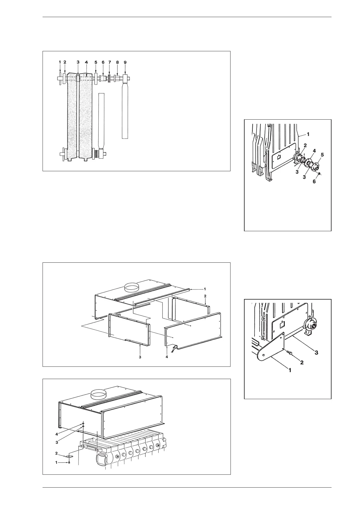
2.7 ASSEMBLING THE FLUE
GAS CHAMBER
The flue gas chamber is supplied in four pie-
ces to be joined with screws supplied (fig. 7).
It is assembled by anchoring the right side
panel (2) to the upper panel (1) with nine
self-tapping TE 12E x 1/2” screws.
The same operation must be performed on
the left side panel (3). Lastly, anchor the cle-
aning panel in place (4).
When assembly is complete, position the flue
gas chamber above the cast iron body. Anchor
the flue gas chamber to the body using the four
plates and the four TE M8 x 30 screws supplied
(fig. 7/a).
2.8 ASSEMBLING THE WATER
DISTRIBUTOR
The water distributor on the return line co
-
ming in from the heating system is located
on the right side of the generator. If it is ne-
cessary to move it to the left side, check that
the two rows of holes in the distributor are
directed upwards and toward the front of the
boiler (fig. 8).
2.9 ASSEMBLING THE BURNER
MANIFOLD
To assemble the burner manifold, screw in
the four TE M8 x 16 screws on the threaded
nibs of the two heads of the boiler body (fig.
9).
2.10 ASSEMBLING THE BURNERS
Once the burner manifold has been assem-
bled, insert the burners in the combustion
chamber one at a time, ensuring that the
slits in the burner are turned upward.
Push so that the burner support goes into
the hole in the cast iron wall and divides the
elements (fig. 10). Anchor the burner to the
manifold with a TCB M5 x 8 screw.
KEY
1 Plug
2 Flange ø 35/87
3 Two-way cone
4 Tie rod L. 900 + tie rod L. 980
5 Flange ø 50/87
6 Pipe segment
7 Thrust bearing
8 Nut
9 Tightening key
Fig. 6
KEY
1 Upper panel
2 Right side panel
3 Left side panel
4 Cleaning panel
Fig. 7
Fig. 7/a
KEY
1 TE M8 x 30 screw
2 Plate
3 Washer ø 8,4
4 Nut M8
KEY
1 Boiler body
2 M12 x 60 stud bolt
3 Seal ø 65/95 x 2
4 Distributor pipe
5 DN50 2” collar flange
6 Nut M12
Fig. 8
Fig. 9
KEY
1 Burner manifold
2 TE M8 x 16 screws
3 Right head
Bekijk gratis de handleiding van Sime RS Mk II, stel vragen en lees de antwoorden op veelvoorkomende problemen, of gebruik onze assistent om sneller informatie in de handleiding te vinden of uitleg te krijgen over specifieke functies.
Productinformatie
| Merk | Sime |
| Model | RS Mk II |
| Categorie | Niet gecategoriseerd |
| Taal | Nederlands |
| Grootte | 12893 MB |


