Sime Murelle 110 BOX ErP handleiding
Handleiding
Je bekijkt pagina 6 van 56
6
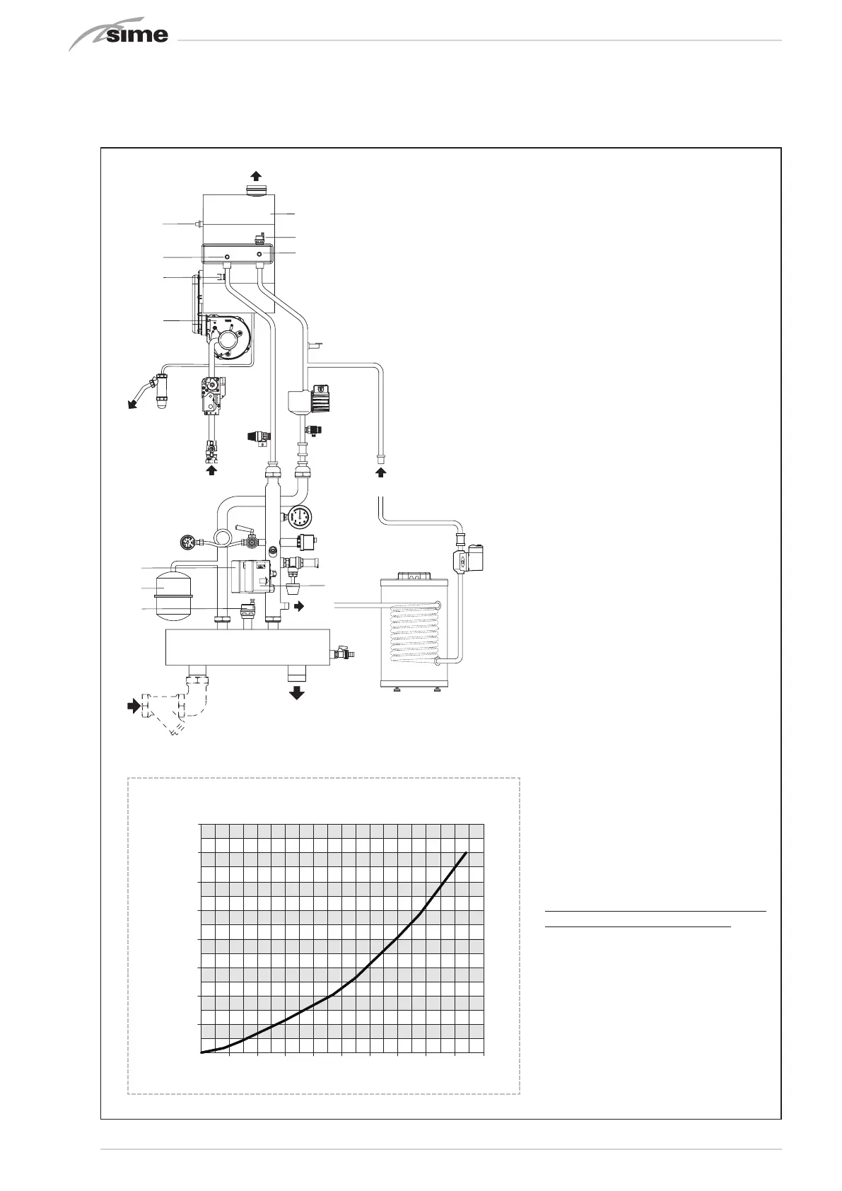
1.4 FUNCTIONAL DIAGRAM (fig. 2)
18
31
29
M2
R3
18
31
29
M2
R3
8
12
3
11
13
14
16
17
1
2
15
21
22
19
20
M
R
G
S3
4
6
5
7
8
12
3
4
6
5
7
11
13
14
16
1
15
17
21
22
30
26
28
27
24
19
20
2
S3
G
R
M
EXPORT
ITALIA
25
23
23
KEY
1 Gas valve
2 Condensate drainage siphon
3 Heating return sensor (SR)
4 Fan
5 Heating delivery probe (SM)
6 Safety thermostat 100°C
7 Flue gas probe (SF)
8 Primary heat exchanger
11 Water pressure transducer
12 Automatic bleed
13 High-efficiency system pump
14 Boiler drain
15 Gas valve (not included)
16 Check valve
17 5 bar system relief valve
18 Check valve (not included)
19 Hydraulic compensator
20 Drain valve
21 8 litre expansion vessel (admissible pre-charge
pressure given in PAR. 1.3)
22 Automatic bleed
23 Oblique filter (not included)
24 Thermometer
25 0-10 bar pressure gauge with valve
26 Water max pressure switch (4 bar)
27 Safety thermostat 100°C
28 4.5 bar relief valve
29 Storage tank (not included)
30 Water min pressure switch (0.9 bar)
31 Storage tank pump (not included)
FITTINGS
M System delivery
R System return
G Gas
S3 Condensate outlet
M2 Hot water tank delivery
R3 Hot water tank return
600
1000
4500
400035003000250020001500
PORTATA (l/h)
PERDITE DI CARICO TRA
GLI AT TACCHI R3 e M2 (mbar)
500
400
100
200
300
700
800
5000
5500
Murelle HE 92.5 R ErP
Murelle HE 110 R ErP
600
200
1600
140012001000800600400
PORTATA (l/h)
PERDITE DI CARICO TRA
GLI AT TA CCHI R3 e M2 (mbar)
500
400
100
200
300
Murelle HE 50 R ErP
Murelle HE 70 R ErP
2200
20001800
600
200
1600
140012001000800600400
PORTATA (l/h)
PERDITE DI CARICO TRA
GLI AT TA CCHI R3 e M2 (mbar)
500
400
100
200
300
700
800
Murelle HE 35 R ErP
LOAD/FLOW RATE LOSS CURVES BETWEEN FITTINGS R3 AND M2
Fig. 2
WARNING:
The storage tank pump (31) must be
rated for the domestic hot water cir-
cuit losses (tank and pipes) and the
minimum required flow rate (3,800
l/h).
The tank (29) must be controlled by an
RVS controller (configure the installer
parameter PAR 10).
For indoors installations of the
MURELLE 110 BOX ErP ONLY,when
hooking up the tank (29):
- configure installer parameter PAR
2=6.
- hook up the storage tank pump (31)
to terminals 18-20 of connector CN9
on the boiler board.
- move the capillary from the siphon
antifreeze probe (2) to the boiler so
that it acts as a hot water tank sensor.
FLOW RATE (l/h)
LOAD/FLOW RATE LOSS CURVES
BETWEEN FITTINGS R3 and M2 mbar
Bekijk gratis de handleiding van Sime Murelle 110 BOX ErP, stel vragen en lees de antwoorden op veelvoorkomende problemen, of gebruik onze assistent om sneller informatie in de handleiding te vinden of uitleg te krijgen over specifieke functies.
Productinformatie
| Merk | Sime |
| Model | Murelle 110 BOX ErP |
| Categorie | Niet gecategoriseerd |
| Taal | Nederlands |
| Grootte | 8842 MB |


