Sharp NU-RD300 handleiding
Handleiding
Je bekijkt pagina 6 van 13
6
CAUTION!
Hot module parts in strong sunlight. Risk of
burning!
• Protect yourself from burning by wearing gloves and
suitable clothing.
5 Mechanical Installation
5.1 Mounting orientation for PV modules
For roof top installations, install the PV modules on fire
resistant roofs only. Please note that additional fire
proofing might be required, depending on local building
/ fire codes.
5.1.1 Vertical (portrait) mounting
When mounting the PV module vertically, make sure
that the exit holes for the cables on the junction box
are facing towards the ground.
5.1.2 Horizontal (landscape) mounting
When mounting horizontally, make sure that the exit
holes for the cables on the junction box are positioned
on the inside of the photovoltaic generator. Avoid the
lateral outer edges of the photovoltaic generator to
minimize the effect of ambient conditions, such as wind
or rain
5.1.3 Inclination
Incline the surface of the PV modules at an angle of at
least 10° horizontally, so that precipitation can drain off
which supports the modules self-cleaning.
For optimum self-cleaning, we recommend an angle of
at least 15° horizontally.
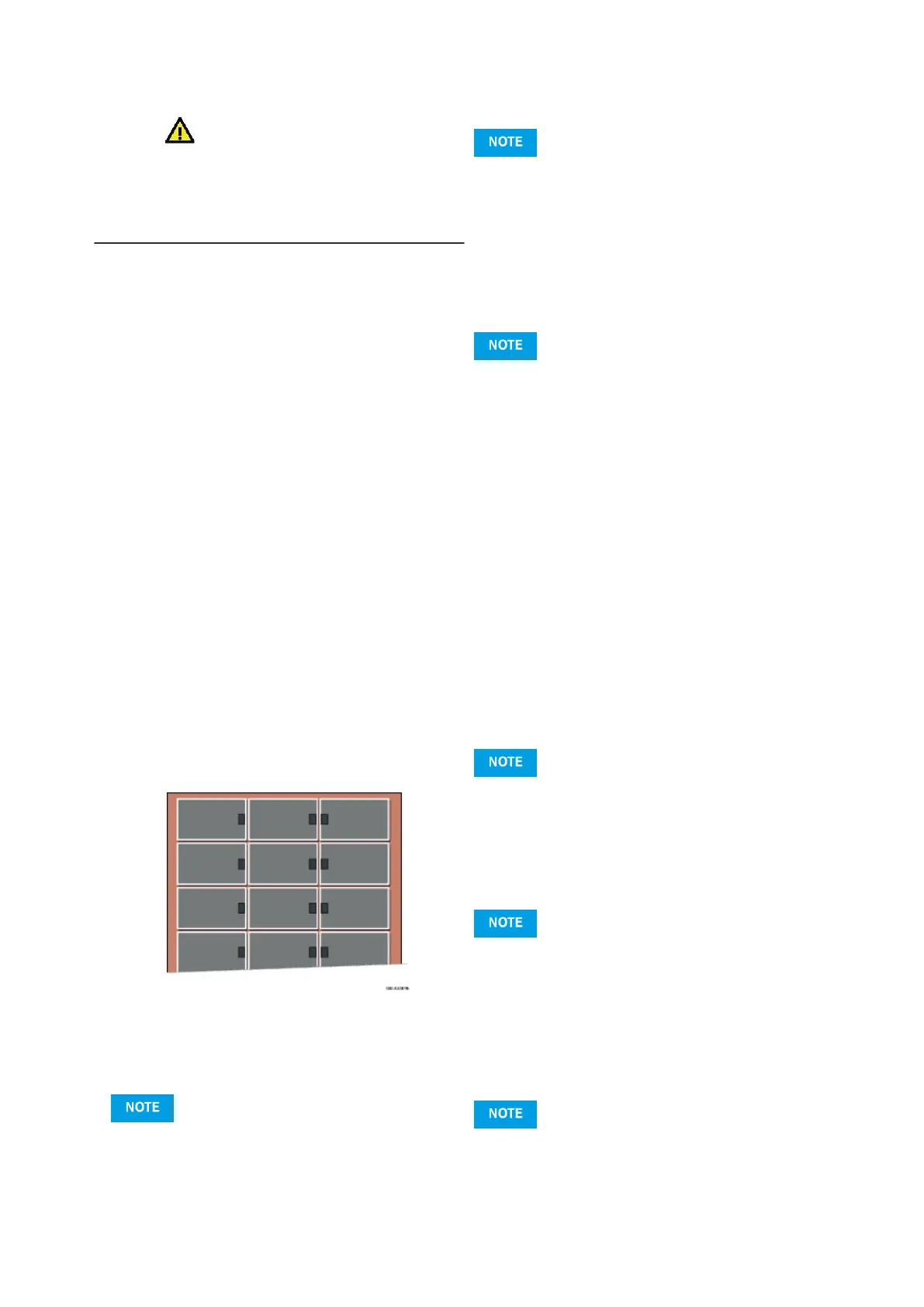
Fig.1
Recommended position of the junction boxes for hori-
zontal mounting (facing the middle of the generator)
5.2 Safety precautions
HINWEIS
Do not drill any additional holes in PV modules or their
frames.
5.3 Improper mounting
INWEIS
• Do not attach the PV modules using nails. The vibra-
tion created in the process can cause micro fissures
and loss of yield, and results in loss of warranty rights.
• Do not attach the modules by welding. The tempera-
tures created in the process can cause delamination,
micro fissures and loss of yield, and results in loss of
warranty rights
5.4 Clearance
5.4.1 Clearance between PV modules
NWEIS
• Leave a minimum clearance when mounting PV
modules.
This prevents mechanical tension due to thermal
expansion.
• When mounting at intervals
Leave a clearance of 3 mm or more between the
individual PV module frames.
• For edge-to-edge mounting
Allow for an expansion joint of 20 mm after a
maximum of 7 m.
• The recommended maximum clearance is 30 cm,
based on the PV modules‘ standard cable length.
SHARP recommends mounting at intervals. Also
note the information the mounting equipment vendor.
This could specify larger intervals
5.4.2 Clearance under the PV modules
■ Minimum clearance
H
• Rooftop or free field mounting
Ensure a clearance of at least 4 cm between the rear
edge of the frame and the mounting surface (e.g. the
roof tiles) for the rear ventilation of the PV module.
■ Maximum clearance
WEIS
• The largest permissible clearance is defined by
national standards. This is used to design the instal
lation on the assumed effects of wind and suction.
• The actual maximum clearance of an installation is
determined by the sub-structure. Ensure that your
sub-structure adheres to the permissible clearances.
5.5 Avoiding seals
HINWEIS
• Avoid the use of a seal between PV modules and
their mounting surface.
Bekijk gratis de handleiding van Sharp NU-RD300, stel vragen en lees de antwoorden op veelvoorkomende problemen, of gebruik onze assistent om sneller informatie in de handleiding te vinden of uitleg te krijgen over specifieke functies.
Productinformatie
| Merk | Sharp |
| Model | NU-RD300 |
| Categorie | Niet gecategoriseerd |
| Taal | Nederlands |
| Grootte | 1935 MB |


