Sauermann TH 210-R handleiding
Handleiding
Je bekijkt pagina 12 van 32
6. F 300: ANALOGUE OUTPUTS MANAGEMENT
6.1. Outputs diagnostic
This function allows to check on a measurement device (multimeter, regulator or automate) the proper functioning of the
outputs. The transmitter will generate a voltage (between 0 and 10 V) or a current (between 0 and 20 mA) according to the
setting of the DIP switch of the transmitter electronic board.
• For a 0-10 V output signal, the transmitter will generate 0 – 5 or 10 V.
• For a 0-5 V output signal, the transmitter will generate 0 – 2.5 or 5 V.
• For a 4-20 mA output signal, the transmitter will generate 4 – 12 or 20 mA.
• For a 0-20 mA output signal, the transmitter will generate 0 – 10 or 20 mA.
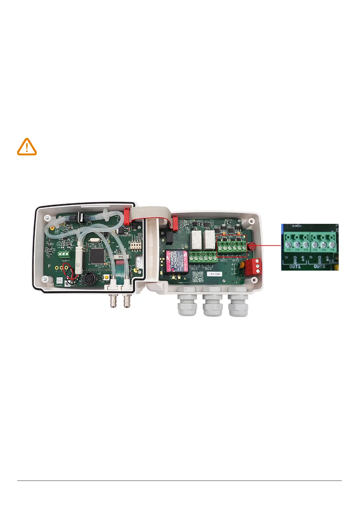
6.1.1 Connection conguration
Before carrying out the output diagnostics, all connections and congurations of the transmitter
must be enabled, to avoid any damage on the transmitter and the measurement device!
➢ Select a channel for the outputs diagnostic.
OUT1 or OUT2, indicated on the electronic board above the terminal blocks.
➢ Connect a measurement device on the channel 1 or on the channel 2.
6.1.2 Perform the outputs diagnostic
Once the connection to the measurement device is complete, the outputs diagnostic on several check points can be
performed:
The transmitter is powered on.
➢ Press OK.
➢ Enter the activation code (see page 8).
➢ Press OK.
➢ Press Up key to go to the “F 300” folder.
➢ Press OK.
“F 301” blinks, corresponding to the diagnostic of the channel 1.
➢ Press OK.
➢ Press Up and Down keys to select the signal that the transmitter has to generate.
12
F 300: ANALOGUE OUTPUTS MANAGEMENT
Bekijk gratis de handleiding van Sauermann TH 210-R, stel vragen en lees de antwoorden op veelvoorkomende problemen, of gebruik onze assistent om sneller informatie in de handleiding te vinden of uitleg te krijgen over specifieke functies.
Productinformatie
| Merk | Sauermann |
| Model | TH 210-R |
| Categorie | Niet gecategoriseerd |
| Taal | Nederlands |
| Grootte | 3582 MB |


