Handleiding
Je bekijkt pagina 20 van 42
20
English
Installation Procedure
Installation Procedure
• Nitrogen blowing pressure range is 0.02 to 0.05 Mpa.
• If you need a pipe longer than specified in piping codes
and standards, you must add refrigerant to the pipe.
Otherwise, the indoor unit may freeze.
• While removing burrs, put the pipe face down to make
sure that the burrs do not get in to the pipe.
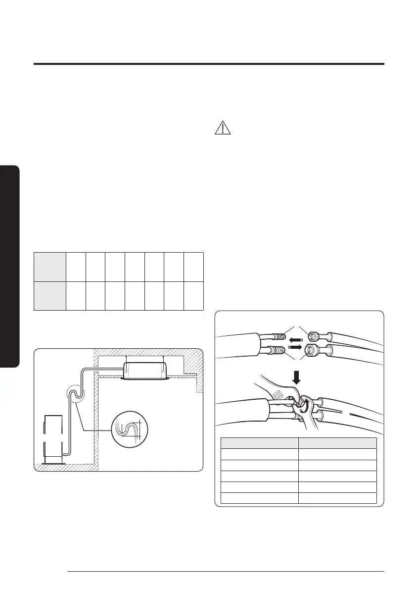
Step 8 Installing oil traps
Check the following list and install an oil trap.
• Based on cooling operation, install it on the gas side
pipe only.
• Install the oil trap only in between the outdoor unit
and the first branch joint and it should be installed at
every 10 m.
• Radius of curvature (R) on the oil trap are as follows;
Pipe
diameter
(D, mm)
12.7 15.88 19.05 22.23 25.4 28.6 31.75
Radius of
curvature
(R, mm)
25 and
over
32 and
over
38 and
over
41 and
over
51 and
over
57 and
over
60 and
over
• Height of the oil trap (H): 4R ≤ H ≤ 6R
• When the indoor unit is installed at a higher place than
the outdoor unit
Indoor Unit
Outdoor Unit
Oil trap
(Install it at every
10 m)
R
H
Step 9 Connecting up and removing air in
the circuit
CAUTION
• When installing, make sure there is no leakage. When
recovering the refrigerant, ground the compressor first
before removing the connection pipe. If the refrigerant
pipe is not properly connected and the compressor works
with the service valve open, the pipe inhales the air and
it makes the pressure inside of the refrigerant cycle
abnormally high. It may cause explosion and injury.
The air in the indoor unit and in the pipe must be evacuated.
If air remains in the refrigerant pipes, it will affect the
compressor either reduce cooling/heating capacity or lead to
a malfunction. Use Vacuum Pump as shown on the next page
figure.
1 Connect each assembly pipe to the appropriate valve on
the outdoor unit and tighten the flare nut.
2 Referring to the illustration below, tighten the flare nut on
section D first manually and then with a torque wrench,
applying the following torque.
Outer Diameter (mm) Torque (N·m)
ø6.35 14 to 18
ø9.52 34 to 42
ø12.70 49 to 61
ø15.88 68 to 82
ø19.05 100 to 120
A (Gas)
Outdoor Unit
B (Liquid)
C
D
3 Connect the charging hose of low pressure side of
manifold gauge to the packed valve having a service port
as shown at the figure.
Bekijk gratis de handleiding van Samsung AC100BXADGH, stel vragen en lees de antwoorden op veelvoorkomende problemen, of gebruik onze assistent om sneller informatie in de handleiding te vinden of uitleg te krijgen over specifieke functies.
Productinformatie
| Merk | Samsung |
| Model | AC100BXADGH |
| Categorie | Airco |
| Taal | Nederlands |
| Grootte | 6274 MB |


